Camera Image Input HDRFH/FZ5 Processing Item Function Reference Manual
75
1
Input image
Electronic Flash Setting
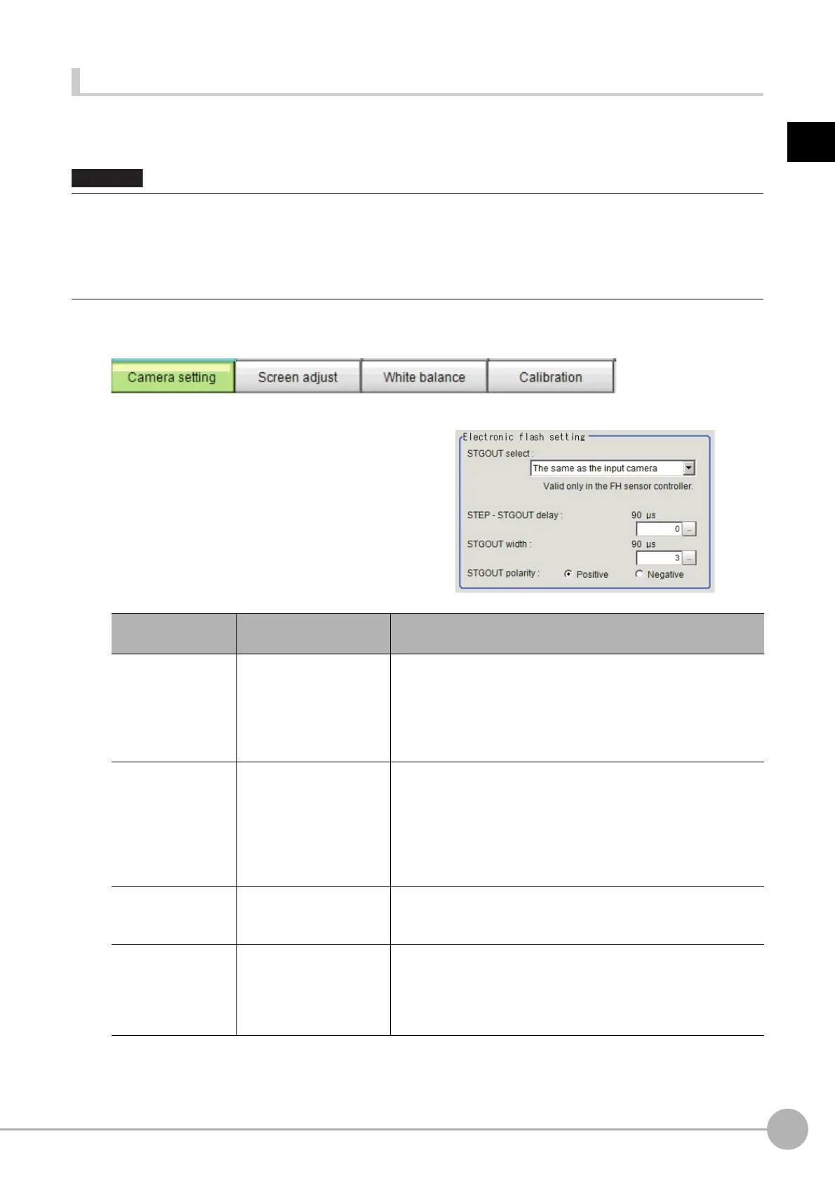
This function is set when an electronic flash is used. This sets the output conditions for the signal for
synchronizing the measurement and the electronic flash timing.
1 In the Item Tab area, click [Camera setting].
2 In the Electronic flash setting area, set
the items of STGOUT signals.
• The STGOUT signals that can be output are as follows.
: FH-1000 and FH-3000 series: SGTOUT 0 to 7
: FH-L series: STGOUT 0 to 3
• STGOUT0 to STGOUT7 is tied to The camera
connector number of the sensor controller, not the camera number.
When you use CameraLink Medium Configuration
or the Multi-line random-trigger mode, confirm the camera connector
number that corresponds to the camera number of sensor Controller.
Item
Setting value
[Factory default]
Description
STGOUT select
[The same as the input
c
a
mera]
Camera 0 to 7
Select the STGOUT signal to use for Camera Image Input HDR
processing item.
The same as the input camera: STGOUT
that is
tied to the input
camera is output.
Camera 0 to 7: STGOUT signal that is tied to the selected camera
is output.
STEP-STGOUT
de
lay
[0]
to 511
(1 count is 30μs)
Set the time to wait to turn ON the electronig flash trigger signal
af
te
r STEP signal is input.
Delay time = count number ×30μs+90μs
Delay time changes with the setting of STGOUT polarity.
The time displayed is for the polarity
of Positive; for
Negative,
35μs will be added to the displayed time.
Delay time is within the range ±10μs of
set value.
ST
GOUT width
0 to 43689
[3]
(1count is 30μs)
Set the time to output the electronic flash trigger signal.
For FH series controller, set 0 to disable flashing.
STGOUT polarity
• [Positive]
• Negative
Set the pulse polarity of electronic flash trigger.
Positive: flashes synchronizing with the electronic flash trigger
outpu
t changing from OFF→ON.
Negative: flashes synchronizing with the electronic flashing trigger
outpu
t chan
ging from ON→OFF.

 Loading...


