Stage Data
730
FH/FZ5 Processing Item Function Reference Manual
Set parameters depending on each of Stage (X(Y) Stage)
In this setting area, set X Stage and Y Stage.
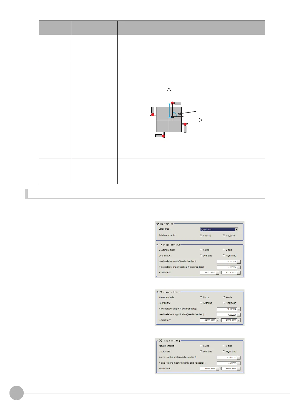
1 Selecting [XY stage] in [Stage type], [XY
stage setting] is displayed.
Set parameters in [XY stage setting] area.
2 Select type of Stage in [Movement axis]
in [X(Y) stage setting] area.
Selecting [X-axis] as [Movement axis] and set
[Y-axis] to X stage, then [Y-axis] is set to Y
stage.
Parameter name in [X(Y) stage setting] area
will change
depending on selected [Mov
ement
axis].
*1, *2, *3
θ3
-360.000000 to
360.000000
[0.000000]
Set the angle from the X axis of the line segment connecting the stage
rotation center and W axis pivot point in the return to origin (each axis'
movement amount is 0) status. As for the angle, the X axis is set to 0° and
the direction from X axis forward to Y axis forward is set to +.
R4
0.000000 to
99999.999999
[0.000000]
Set the length of line segment connecting the stage rotation center and R
axis pi
vo
t point in the return to origin (each axis' movement amount is 0)
status.
θ4
-360.000000 to
360.000000
[0.000000]
Set the angle from the X axis of the line segment connecting the stage
rotation center and R axis pivot point in the return to origin (each axis'
movement amount is 0) status. As for the angle, the X axis is set to 0° and
the direction from X axis forward to Y axis forward is set to +.
Setting item
Setting value
[Factory default]
Description
R4
θ
4
R axis pivot point in return to
origin state
X axis
U axis
V axis
R axis
W axis
Y axis
Rotation center
XY coordinate system that
becomes parallel or vertical
to UVWR axes
When you select [X-axis]
When you select [Y-axis]

 Loading...


