1/05
10-7
DocuColor 12/DCCS50
Principles of Operation Overview
Principles of Operation
Reissue
Local User Interface
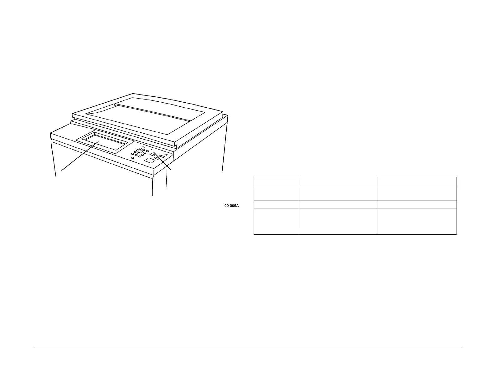
The local User Interface, shown in Figure 2, includes the Control Panel, the optional Edit Pad
Assembly and the electronics associated with these assemblies. The User Interface sends
operator commands to Machine Run Control, and displays messages and graphics in
response to commands from Machine Run Control. The displayed messages and their lan-
guage can be changed by downloading software from a Portable Workstation (PWS) con-
nected at the rear of the machine.
Figure 2 User Interface
Remote User Interface
When the machine is configured as a printer or Copier/Printer/Scanner, its Digital Front End
(DFE) appears as an Internet or Intranet server. Users can send their print jobs to the machine,
and retrieve images, which have been scanned from the Platen Glass.
Machine Run Control
Machine Run Control is the hardware and software that controls machine printing and copying
operations. It accepts status information from all machine subsystems and controls their oper-
ation. Specifically, Machine Run Control performs the following functions:
• It analyzes and implements operator inputs from the User Interface and sends display
messages
for the operator to the User Interface.
• It receives status inputs from machine sensors and prov
ides timing and sequencing
instructions to machine motors and clutches.
• It identifies machine faults, initiates appropriate recovery operations and notifies the oper-
ator.
• It provides cycle-up and cycle-down commands to all other subsystems.
Start Power
Start Power refers to the motors and drives which are activated when the START button is
pressed on the User Interface, or downloads a print file from a remote user workstation. Start
Power is comprised of the Main Motor and the Photoreceptor Motor and their associated driv-
etrains. However, these two motors do not provide all of the mechanical drive in the machine.
Mot
ors
powering other machine subsystems are described in the chapters associated with
these subsystems.
Document Transportation
In a machine configured as a Copier or Copier/Printer/Scanner, the document is placed on the
Platen Glass. This can either be done manually by the user or automatically by the Duplex
Automatic Document Feeder (DADF) (Figure 4). In both cases, the machine can automatically
determine the size of the original document.
A machine configured as a Copier/Printer/Scanner can also sc
an document
s, and the resulting
images are routed to a user client workstation by the DFE.
Imaging
Imaging is the acquisition and processing the document image, up to being written to the Pho-
toreceptor Drum. As shown in Table 1,
the source and destination of the image depends on the
machine configuration.
Scan and copy images are created at the IIT when the Xenon lamp illuminates the original doc-
ument on the Platen Glass, and the Charge Coupled Device (CCD) samples the document at
400
dots
per inch (DPI). The image is then manipulated by the Image Input Terminal (IIT) and
the Image Processing System (IPS):
1. They determine if the original docum
ent
is color or monochrome
2. They digitize the analog data from the CCD
3. They separate the image into its component colors
4. They perform any other processing, such as image
enlargement or reduction, that the
user has specified
When copying, the image is routed to additional processing circui
try in the Image Output Termi-
nal (IOT). The IOT circuitry drives the laser diode in the Raster Output Scanner (ROS). This
diode wr
ites the latent image onto the Photoreceptor Drum.
TOUCH PAD and
LEDS
LCD TOUCHSCREEN
Table 1 Image Sources and Destinations
Configuration Image Sources Image Destinations
Printer User workstation via LAN and
DF
E
Photorecept
or Drum
Copier IIT Photoreceptor Drum
Copier/Printer/
Scanner
IIT
or
User
workstation via LAN and
DF
E
Photorecept
or Drum
or
User workstation via DFE and
LAN

 Loading...


