1/05
10-151
DocuColor 12/DCCS50
Print Transport through the Mailbox/Sorter
Principles of Operation
Reissue
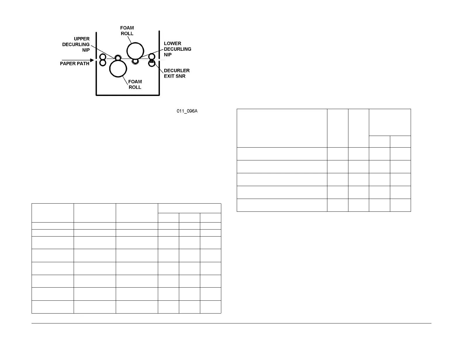
Figure 1 Paper Decurling components and function
Therefore, prints exiting with image side down are forc
ed through the Upper Decurling Nip with
2, 6 or 10 mm of shift and through the Lower Decurling Nip with no nip shift. The controls
required for this function originate in the machine IOT CPU PWBA. This information is then
sent through the Mailbox/Sorter Control PWBA to the Decurler Control PWBA. This last PWBA
regulates the amount of Nip Shift and which nip is shifted. Ta b le 2 shows the distance of the
Nip Shift in the Decurling Roll for various paper types and copy modes.
The Decurler transport speed is to match the transports speed of the copy job through the
xerogr
aphics proces
s. The speed of the Decurler Motor is determined by the IOT CPU PWBA.
OCT Gate Control
The OCT Gate is moved up or down by the OCT Solenoid. This gate diverts the copy material
to either the bins or to the OCT. The status of the OCT Gate is determined by the IOT CPU
PWBA, which sends an appropriate message to the Mailbox/Sorter Control PWBA. The Mail-
box/Sorter Control PWBA enables or disables the OCT Solenoid as required.
Mailbox/Sorter Control
The sorter and mailbox functions use the same hardware. The difference between them results
from the configuration of the attached machine and the type of print or copy job being per-
formed. These differences result in different control messages from the IOT CPU PWBA and
dif
ferent
control signals from the Mailbox/Sorter Control PWBA. In particular, the machine con-
figuration determines whether sorter or mailbox f
unct
ionality is available. Table 3 shows the
types of collating functions that are available for the different machine configurations.
Sorter Functions
NOTE: Sorter operation is possible only when the Mailbox/Sorter is attached to the Digital
Copier machine (DC).
When a Sorter is connected to the Digital Copier, four (4
) different finishing outputs are avail-
able. See Table 3 f
or these outputs.
When the Mailbox/Sorter is configured as a Sorter, the user c
an select from the User Interface
screen either Sort Mode or Stack Mode for outputs to the bins. Copies for bin output are
diverted into the Vertical Transport area of the Sorter by the OCT Gate. At the appropriate bin
level, a bin solenoid energizes to push a Bin Diverter Gate (one gate per output bin) into the
paper path. This directs the copy into that bin. The selection of the Bin Diverter Gate is made
by the Sorter Control PWBA in response to control messages from the IOT CPU PWBA. The
appropriate Bin Solenoid is energized only as the copy enters the vertical transport area. When
the trailing edge of the copy passes the Bin Sensor, the Bin Solenoid deenergizes to close the
Bin Gate.
Table 2 Decurler Shift Requirements & Motor Speeds
Media Type Image Type Transport Speed
Decurler Roll Nip Shift
2 mm 6 mm 10 mm
Transparency Black and White 160 mm/sec X
Transparency 4-Color 60 mm/sec X
Lightweight Plain
Pape
r
Bl
ack + 1 Color 160 mm/sec X
Lightweight Plain
Paper
4-Color; I
mage
Density < 50%
160 mm/sec X
Lightweight Plain
Paper
4-Color; I
mage
Density > 50%
160 mm/sec X
Heavyweight Plain
Paper
Black +
1 color 60 mm/sec X
Heavyweight Plain
Paper
4-Color; I
mage
Density < 50%
60 mm/sec X
Heavyweight Plain
Paper
4-Color; I
mage
Density > 50%
60 mm/sec X
Table 3 Functions for different configurations
Output Functions
Printer
(P
R)
Only
M
ailbox
Copier
(DC)
Only
Sorter
Copier/Printer
(DC/PR)
Mailbox
f
unct
ioning as a:
Copier Printer
Sorts into bins
(1,2,3...1,2,3...etc.)
X
Stacks into bins
(1,1,1...2,2,2...etc.)
X
Sorts into bins by user
(User A: 1,2,3...User B: 1,2,3...etc.)
X X
Offset Catch Tray (OCT)
straight stack
X X X X
Offset Catch Tray (OCT)
offset stacks
X X X X

 Loading...


