1/05
10-41
DocuColor 12/DCCS50
Self-test, PWBA LEDs
Principles of Operation
Reissue
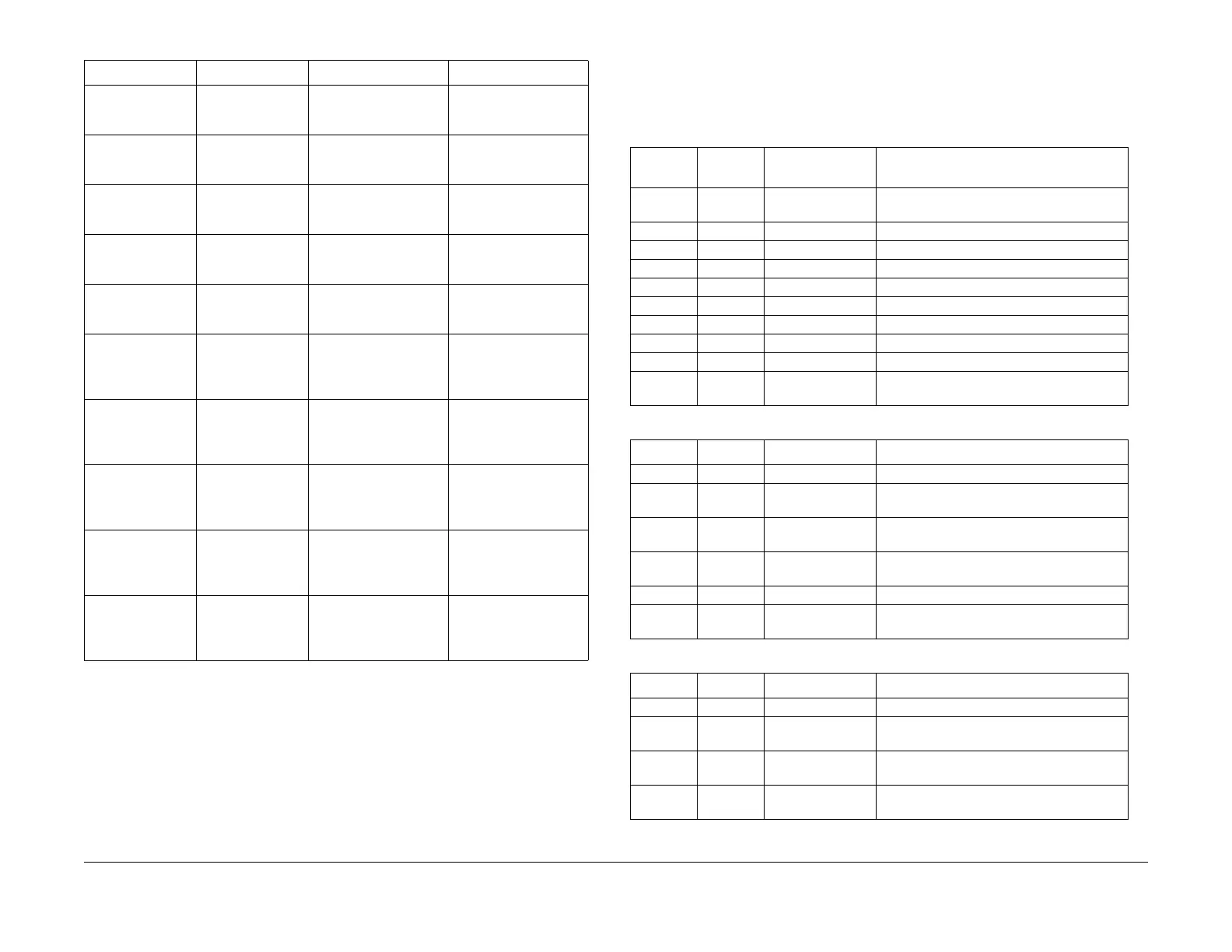
PWBA LEDs
Table 1, Table 2, Table 3, Table 4, Table 5, Table 6, Table 7, and Table 8 list the diagnostic
LEDs on various machine PWBAs. These can be used to determine the status of both on-
board and off-board circuitry.
Printer Interface
D
DI
Comms Test 2
End-to-End
Comms test to IOT
CPU PWBA
Failure LED doesn’t
bl
ink pattern
Failure LED blinks pat-
tern 2, but software boot
continues
Sc
an Out Interface
DDI
Comms Test 1
UART (internal
loopback)
Client level command to
IOT
Failure LED blinks pat-
tern 3, but printer oper-
ates normally
Scan Out Interface
D
DI
Comms Test 2
End-to-End
Comms test to IOT
CPU PWBA
Failure LED doesn’t
bl
ink pattern
Failure LED blinks pat-
tern 4, but printer oper-
ates normally
Network/connec-
tivity Hardware,
part
1
Netw
ork link hard-
ware
Link LED stays lit Link LED isn’t lit
Network/connec-
tivity Hardware,
part
2
Netw
ork visibility to
ID
FE
Act
ivity LED flashes pat-
tern mimicking network
traffi
c flow
Activity LED does not
fl
as
h
Network/connec-
tivity Hardware,
part
3
Ethernet
speed
det
ec
tion circuitry
Configuration report,
web client and XCMI
setting contain correct
speed connection
Configuration report,
web c
lient and XCMI
setting contain incor-
rect speed connection
Network/connec-
tivity Hardware,
part
4
Token Ring
speed
det
ec
tion circuitry
LED or other media dis-
plays sensed or set
speed connection
LED or
other media indi-
cates wrong speed con-
nection. Desired speed
can be
set
manually
Network/connec-
tivity Software, part
1
TCP/IP connectiv-
ity and SMB test
using P
ing f
unc-
tionality
At least 1 ICMP echo
respons
e is
received
and message is printed
on configuration report
No response is
received;
message
printed on configuration
report
Network/connec-
tivity Software, part
2
Netware connec-
tivity using Get-
NearestServer
f
uncti
onality
A GetNearestServer
response is
received
and message is printed
on configuration report
No response is
received;
message
printed on configuration
report
Network/connec-
tivity Software, part
3
Appletalk connec-
tivity using Get-
MyZone
f
uncti
onality
A Zone response is
received and message
i
s printed on configura-
tion report
No response is
received;
message
printed on configuration
report
Table 1 IDFE Power-On Self-Test
T
est
Performed What’s Tested Pass Indication Fail Indication
Table 1 IOT CPU PWBA LEDs
LED Color Signal Comment
CR5 Red CPU Reset Lit indicates that reset line to CPU is being
asserted
CR6 G
reen PWS Rx Data Flickering indicates data transitions
CR7 Green Tray 6 (HCF) Flickering indicates data transitions
CR8 Green ESPV Rx Data Flickering indicates data transitions
CR9 Green Decurler Rx Data Flickering indicates data transitions
CR10 Green +5 VDC Lit indicates presence of PWBA power
CR14 Green UI PWBA Tx Data Flickering indicates data transitions
CR16 Green UI PWBA Rx Data Flickering indicates data transitions
CR17 Green IIT PWBA Rx Data Flickering indicates data transitions
CR18 Green IPS PWBA Rx
Dat
a
Flick
ering indicates data transitions
Table 2 Pre-IPS PWBA LEDs
LED Color Signal Comment
CR5 Green T1 Firmware check
CR6 Green IIT_CMD, SYS Flickering indicates command being
received from I
OT
CR7 Green ADF_SYS, ADF Flickering indicates status information being
received f
rom DADF
CR8 Green LED_MEM_RDY,
MRDY
Lit indicates that MEM_RDY signal is active
CR9 Red RST_LED, RST Lit indicates that reset line from IOT is active
CR10 Red CPU_HG, MRST Not lit when CPU firmware operating cor-
rectly
Table 3 Memory System PWBA LEDs
LED Color Signal Comment
CR1 Yellow POWER Indicates +3.3 VDC is present on the PWBA
CR2 Yellow IPSPSI/IPS-PS Page Sync signal from POST to MEMORY, lit
when
si
gnal is active
CR3 Yellow CPE_PS/CMM-
PS(B)
Ou
tput Page Sync signal from CMM1 (blue),
Lit when signal is active.
CR3 Yellow CMMPSG/CMM-
PS(G)
O
utput Page Sync signal from CMM2
(green), Lit when signal is active.

 Loading...


