1/05
10-42
DocuColor 12/DCCS50
PWBA LEDs
Reissue
Principles of Operation
CR4 Yellow CMMPSR/CMM-
PS(R)
Output Page Sync signal from CMM3 (red),
Lit when signal is active
CR5 Yellow IIT-PS/IITPSI Page Sync signal from Pre-IPS to memory.
Lit w
hen signal is active.
CR6 Yellow nMEMRDYd/
nMEMRDY
Li
t indicates that memory can be written to.
CR7 Yellow DRRE Lit indicates that memory can be red from
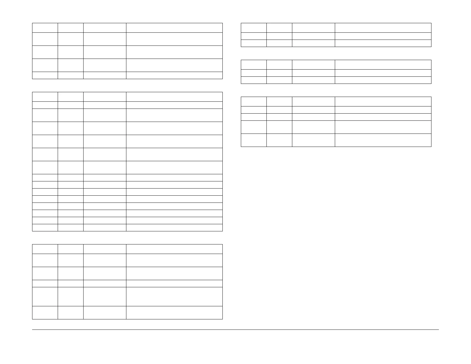
Table 4 Post-IPS PWBA LEDs
LED Color Signal Comment
CR1 Yellow /IPSRST IPS Reset from IOT CPU PWBA
CR2 Yellow /LIPS-STAT From Post-IPS PWBA CPU; Status output to
I
OT
CPU PWBA
CR3 Yellow /IPS-CON Control input from IOT CPU PWBA; after
buffe
r
CR4 Yellow /LIOTEPS1 Page Sync from IOT CPU PWB to Post-IPS
PWBA.
Lit when signal is active.
CR5 Yellow /LIOT\PS0 Page Sync from Post-IPS PWBA to IOT CPU
PWBA
CR6 Ye
llow LSFMSP0 Output Page Sync signal from SFM1 ASIC.
Lit w
hen signal is active.
CR7 Yellow LED0, TIOCA3 From Post-IPS PWBA CPU
CR8 Yellow LED1, TIOCB3 From Post-IPS PWBA CPU
CR9 Yellow LED2, TIOCC3 From Post-IPS PWBA CPU
CR10 Yellow LED3, TIOCD3, From Post-IPS PWBA CPU
CR11 Yellow LED4, TIOCA4 From Post-IPS PWBA CPU
CR12 Yellow LED5, TIOCB4 From Post-IPS PWBA CPU
CR13 Yellow LED6, TIOCA5 From Post-IPS PWBA CPU
CR14 Yellow LED7, TIOCB5 From Post-IPS PWBA CPU
Table 5 IDFE Motherboard LEDs
LED Color Signal Comment
<To Be
Supplied>
Gre
en Power Indicates DC power available to Mother-
board
<To Be
Supplied>
Gre
en Link Indicates integrity of Ethernet connection
Yellow Activity Indicates activity on the Ethernet connection
Red Failure Software controlled with various patterns;
indica
tes fault detection Drente software
boot-up sequence test
Yellow Heartbeat Software controlled with stable pattern; indi-
cates proper operation of software
Table 3 Memory System PWBA LEDs
LED
Co
lor Signal Comment
Table 6 IDFE Print Server LEDs
LED Color Signal Comment
Link Indicates integrity of Ethernet connection
Activity Indicates activity on the Ethernet connection
Table 7 IDFE BNC Transceiver LEDs
LED Color Signal Comment
Link Indicates integrity of Ethernet connection
Activity Indicates activity on the Ethernet connection
Table 8 Edit PWBA LEDs
LED Color Signal Comment
CR1 Yellow +3.3 VDC Indicates presence of +3.3 VDC to PWBA
CR2 Yellow +5 VDC Indicates presence of +5 VDC to PWBA
CR3 Yellow CPE_PS Page Sync signal from Post-IPS PWBA to
Edi
t PW
BA
CR4 Yellow PS0 Page Sync signal from Edit PWBA to Post-
IPS PWBA
manuals4you.commanuals4you.com

 Loading...


