1/05
10-43
DocuColor 12/DCCS50
PWBA Test Points
Principles of Operation
Reissue
PWBA Test Points
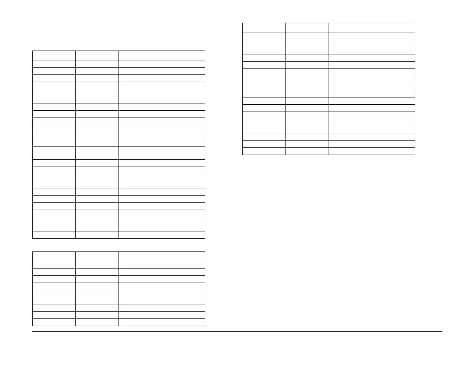
As shown in Table 1 and Table 2, some of the PWBAs contain test points which can be moni-
tored.
Table 1 IOT CPU PWBA Test Points
Test Point Level Comment
TP2 TTL Send data to PWS
TP3 TTL Receive data from PWS
TP4 TTL Send data to IIT
TP5 TTL Send to EPSV (FX only)
TP6 TTL Send to Tray 6 (HCF)
TP7 TTL Send to Decurler
TP8 TTL Receive from IIT
TP9 TTL Receive from IPS
TP11 TTL Receive from UI
TP12 TTL Receive from EMB Scan
TP13 +5V DC Power Input
TP14 TTL Receive from EMB Print
TP15 TTL Receive from Dual Device Interface
(DDI) S
can
TP1
6 TTL Receive from DDI Print
TP17 TTL Send to DDI Print
TP18 TTL Send to DDI Scan
TP19 TTL Send to EMB Print
TP20 TTL Send to EMB Scan
TP21 0 V Ground
TP22 +5V DC Power Input
TP23 ---- Not Used
TP24 TTL Send to UI
TP25 TTL Send to IPS
TP26 0 V Ground
Table 2 IOT Drive PWBA Test Points
Test Point Level Comment
TP1 +5VDC VAREF
TP2 TTL /Fuser On
TP3 TTL PCC_AC_PWH
TP5 0 to +5VDC PR_DH_Sys, From Fuser
TP6 0 to +5VDC Sys_Ext_H/R_Cont From Fuser
TP7 0 to +5VDC Temp_Air_Therm1
TP8 0 to +5VDC HR_On_Sys From Fuser
TP9 Ground 12V Return
TP10 -12VDC Supply Input
TP11 +5VDC IC Supply Voltage
TP12 Ground IC Supply Ground
TP13 Ground IC Supply Ground
TP14 +5VDC IC Supply Voltage
TP15 0 to +5VDC HR_Cont_Sys From Fuser
TP16 0 to +5VDC E_HR_Cont_Sys
TP17 +12VDC Supply Input
TP18 +24VDC Interlocked Supply Input
TP19 0 to +5VDC PR_Cont_Sys
TP20 0 to +5VDC ADC_SNR_VP
TP21 0 to +5VDC ADC_SNR_V_DIF
TP22 TTL ADC_LED_ON
TP23 0 to +5 VDC DTS_DC_V_MONI
TP24 0 to +15 VDC 2BTR_V_MONI
TP26 0 to +5VDC Pre Reg1 Snr
TP27 0 to +5VDC Reg1 Snr
TP28 +24VDC Supply Input
Table 2 IOT Drive PWBA Test Points
T
est P
oint Level Comment
 Loading...


