1/05
10-103
DocuColor 12/DCCS50
Paper Feeders
Principles of Operation
Reissue
• When rotating clockwise, it raises the Tray Lifter in the Paper Tray.
• When rotating counterclockwise, it rotates the Nudger and Feed Rolls for the tray.
The Feed Motors are controlled by the IOT Control and Drive PWBAs. The circuit is the same
for
all four Paper Trays and their Feeder Assemblies. See Figure 2 for the electrical schematic.
The paper feed process starts either when:
• The machine functioning as a printer, receives a print job from the network connection.
• The machine functioning as a copier, the user enters a print job on the User Interface cor-
rectly, provides the document in the Document Feeder or on the Platen Glass and
presses t
he Start Button, and there is the correct copy material in one of the paper supply
sources.
Paper Feed
The IOT Control PWBA manages paper feed timing using the TR0 signal from the IBT Belt as a
reference. In the selected tray, the Feed Motor is energized, rotating the Nudger Roll, and the
Feed Roll. The Retard Roll rotates by being cammed against the Feed Roll. For each sheet of
paper to be fed, the Nudger Roll solenoid momentarily activates, allowing a spring to push the
Nudger Roll down to the top sheet of paper in the tray. The Nudger Roll feeds the paper into the
nip of the Feed/Retard Roll. The paper is fed at a rate of 300 mm/sec. to the Take Away Rollers.
If the lead edge of the paper is not sensed by the Pre-Feed Sensor within the correct time dura-
tion, then a Feed Sensor jam is declared. (See Tray Level Lift and Sensing for maintaining the
p
aper level
in the Paper Trays)
Retard Roller Operation
The Retard Roll prevents more than one sheet of paper from being fed into the paper path at
the same time.
The Retard Roll in each Paper Tray is classified as a semi-active type. The Retard Roll is
mechanically camm
ed against the motor-driven Feed Roll when the Paper Tray is inserted into
the machine. The rotation of the Retard Roll comes from this contact with the Feed Roll.
A friction clutch on the shaft of the Retard Roll provides rotation resistance. When there is no
copy
, or a single sheet
of copy in the nip of the Retard/Feed Roll, the resistance from the fric-
tion clutch is not enough to prevent the Retard Roll from rotating with the motor-driven Feed
Roll.
Th
is allows the rotating Retard and Feed Rolls to feed a single sheet of copy. If more than
one sheet of copy is fed into the Retard/Feed Roll nip, then the resistance from the Friction
Clutch is greater than the resistance between the multiple sheets of copy. This resistance pre-
vents the Retard Roll from rotating, which holds the extra sheets of copy back in the tray while
only t
he
top copy is advanced by the motor-driven Feed Roll.
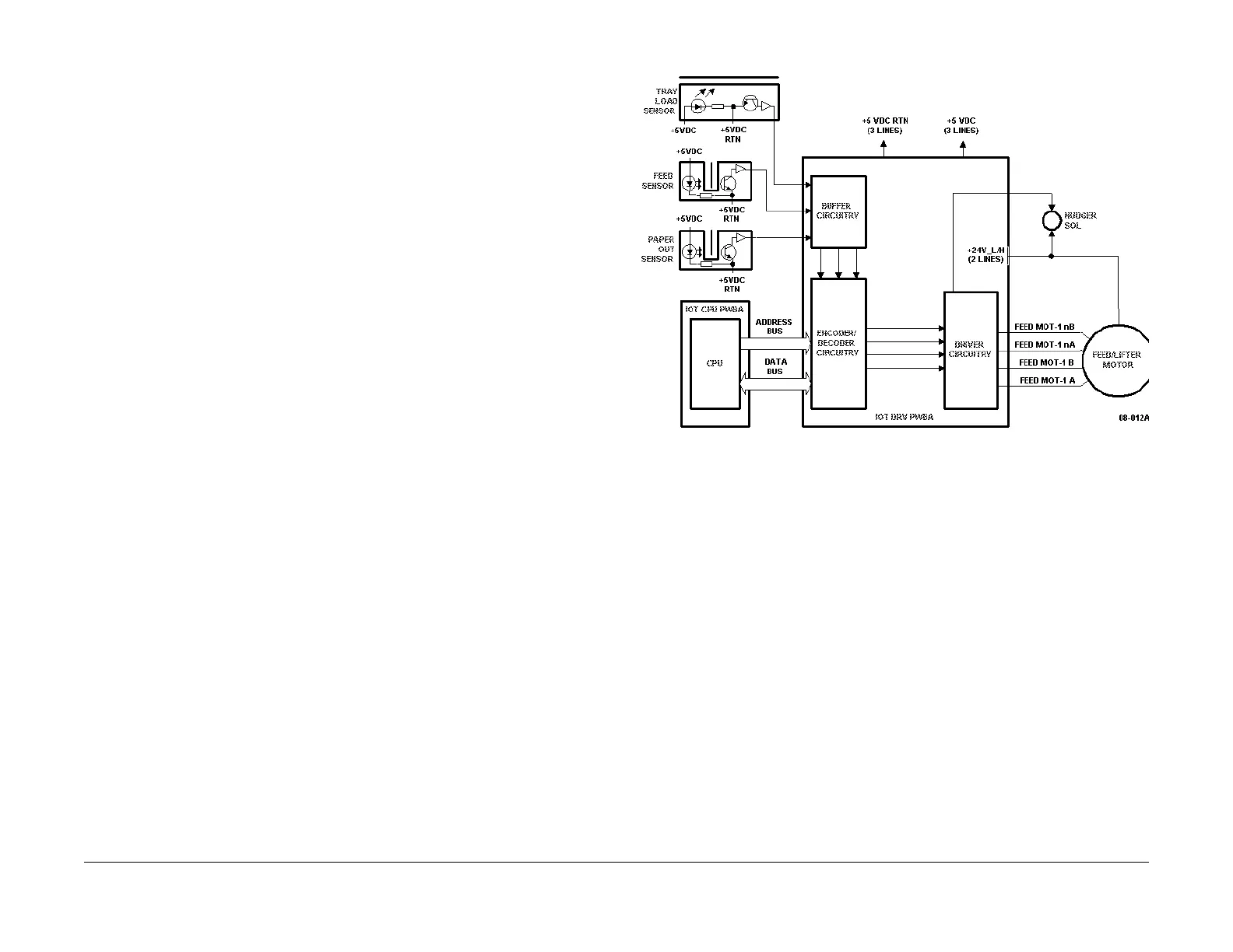
Paper Feed Control
Figure 2 is a partial electrical schematic of the paper feed control.
Figure 2 Partial electrical schematic for paper feed control in Trays 1-4

 Loading...


