1/05
2-230
DocuColor 12/DCCS50
OF19-1 IDFE Fault Entry RAP, 19-001 DC Power Fault
Reissue
Status Indicator RAPs
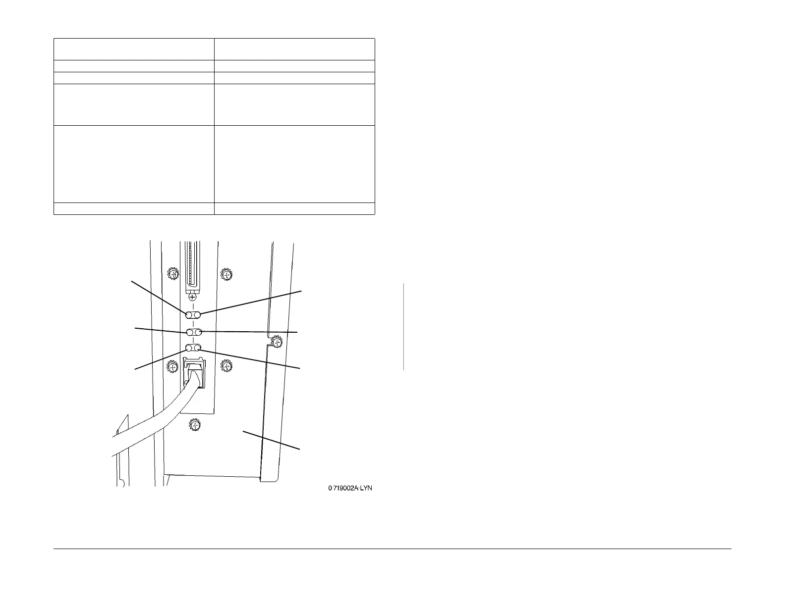
Figure 2 IDFE (MFY) Diagnostic LEDs
19-001 DC Power Fault RAP
NOTE: There are two configurations of the IDFE for this machine. They are identifiable by the
Product Code on the ID tag and by the number of Diagnostic LEDs. Early versions have 5
LEDs and are labeled Product Code GL2. Later versions have 6 LEDs and are labeled Product
Code MFY. This RAP applies generically to both. Where differences between the units exist,
the applicable information is followed by the product code for the specific IDFE.
A 19-001 fault is a DC Power failure to the IDFE. The green Power LED on the IDFE, when de-
energized,
indic
ates a 19-001 fault.
Initial Actions
• Refer to BSD 16.1.
NOTE: Before replacing any of the parts shown in BS
D 16.1, ensure that the connectors
for the parts are correctly seated.
• Inspect and re-seat DC wiring harness connector P/J899 (Flag 1)
. This connector sup-
plies DC power to the IDFE.
• Refer to OF19-1 IDFE Fault Entry Rap, Figur
e 1 (GL2) or Figure 2 (MFY), Diagnostic
LEDs and their locations.
Procedure
PO/PO the machine (GP 8 IDFE Power OFF/Power ON (PO/PO) ). The green Power LED
switches off within 10 sec. of Power-On.
YN
If an intermittent fault is suspected, perform the following:
•Go to F
lag 1 and F
lag 2 of BSD 16.1. Check for loose connections.
• Open the IDFE (GL2 only) and ensure that the Connector for the LED PWBA is cor-
rectly seated.
• Replace the Printer SSR (PL 9.3).
•
Replace the Printer LVPS (PL 9.3).
• Replace the IDFE (PL 1
9.1).
• Check for +5 VDC at, (Flag 1
, Flag 2) 1 through 8.
• Check for +12 VDC at (Flag 1
, Flag 2) 9,11.
•Go to Flag 1
of BSD 16.1, and check for an open/short circuit.
• Go to BSD16.1, Flag 2
, and check for an open/short circuit.
• Replace the Printer SSR (PL 9.3).
•
Replace the Printer LVPS (PL 9.3).
• Replace the IDFE (PL 1
9.1).
Table 6 IDFE (MFY) Diagnostic LEDs - Normal Operation
Green Power LED (PWR) Energizes when DC Power is supplied to the
IDFE
Red Failure LED (ERR) Energizes when the power up sequence fails
Amber Heartbeat LED (HB) Energizes when IDFE software is running
Amber 10/100 LED (100) Energizes when the IDFE is connected to a
10/100B
aseT Ethernet network Solid-ON
indicates 100mbps, LED-OFF indicates
10mbps connection
Green Activity LED (ACT) Energizes when network activity is occurring
o
ver a
10/100 BaseT Ethernet Network
(Refer to Table 5)
NOTE: The Green Link and Amber Diagnos-
tic LEDs only energize when the IDFE is
c
onnecte
d by a 10 or 100 BaseT Ethernet
Network connection.
Red LED Not Used
IDFE (MFY)
Red Failure LED
(ERR)
Amber Heartbeat
LED (HB)
Amber 100/10
Network LED
(100)
Red LED (not used)
Green Power LED
(PWR)
Green Activity LED
(ACT)
manuals4you.commanuals4you.com

 Loading...


