1/05
10-114
DocuColor 12/DCCS50
Development
Reissue
Principles of Operation
Development
NOTE: In common practice, the terms “toner” and “developer” are often used interchangeably,
which can result in confusion. For the purpose of this discussion, the following definitions
apply.
Developer consists of a mixture of toner particles and carrier beads and exists before develop-
ing the latent image on the Photoreceptor Drum.
Toner particles are used to develop the latent image on the Photoreceptor Drum and then
transfers as the final image onto the copy material.
This machine starts with developer (a toner and carrier bead
mixture) within the Toner Car-
tridges and the Developer Housings. For that reason, this documentation will use the term
“developer” th
roughout the Toner Supply processes, and the term “toner” for the developed
image on the Photoreceptor Drum, the IBT and on the copy material.
The Development subsystem consists of four color Dev
eloper Housings m
ounted on a Devel-
oper Rotary Assembly. This Rotary Assembly rotates the four individual color Developer Hous-
ings, one at a time, into position in order to transfer the developer to the electrostatic latent
image
on the P
hotoreceptor Drum. (See Developer Rotary Assembly)
The development method in this machine is call
ed Semi-Conductive Magnetic Brush (S-CMB)
development. It is a compromise between Insulative Magnetic Brush (IMB) and Conductive
Magnetic Brush (CMB). The advantages of IMB and CMB are retained with S-CMB. The disad-
vantages of rough graininess and the CMB disadvant
ages of
brush marks and a non-linear
tone reproduction curve are minimized.
The high negative charge (VH) on the Photoreceptor Drum repre
sents the background, or non-
image area. This will repel the developer, which is charged at -500 to -565 VDC (VBias). This
VBias varies, depending upon humidity and Photoreceptor Drum cycles.
NOTE: Vdev (=VL-VBias) and Vclean (=VH-VBias) are alway
s constant. VBias is changed by
the VH value.
When the Laser beam exposes the image are
a onto the Drum, it reduces the negative potential
charge in the Image area of the drum to approximately -300 VDC (VL). This image area will
attract the negatively charged toner from the Developer Roll, creating a developed image for
that particular color.
The developed image on the Photoreceptor Drum rotates down to the IBT. The developed
image will t
hen t
ransfer from the Drum to the IBT at the First Bias Transfer Roll (1st BTR). If
there is more than one color in the copy job, these colors will follow the same development and
transfer process as just explained, with the different color layers accumulating on top of each
other onto the IBT. When all colors have been transferred to the IBT, then the final image will be
transferred to the paper in one pass. This is done at the Second Bias Transfer Roll (2nd BTR)
which cams up to the IBT, with the copy material passing through this nip.
The developer is delivered from the four Toner Cart
ridges to
the Developer Housings by a sys-
tem of augers. These augers deliver the different toner colors
to a Toner Dispenser which fun-
nels the toner into the appropriate Developer Housings. (See Toner Su
pply.)
Developer Rotary Assembly
The Developer Rotary Assembly contains all four color Developer Housings (YMCK). These
are separated by 90° angles in the Rotary Assembly. A 24 V, 4 Phase Stepper Rotary Motor
drives the assembly. The Rotary Motor is controlled by 3 signals:
• Rotary Motor HIGH
• Rotary Motor ON
• Rotary Motor CLOCK
The Rotary Motor Clock is a pulse output signal coming from the Rotary Stepper Motor. It is
used to det
ermine the Rotary Housing position. The Rotary Assembly rotates once every 2,400
steps.
Braking of the Rotary Assembly is performed by directly cont
rolling the stepping-type Rotary
Motor. In B&W operation, the Rotary Assembly is mechanically locked via a Rotary Latch Sole-
noid and gear.
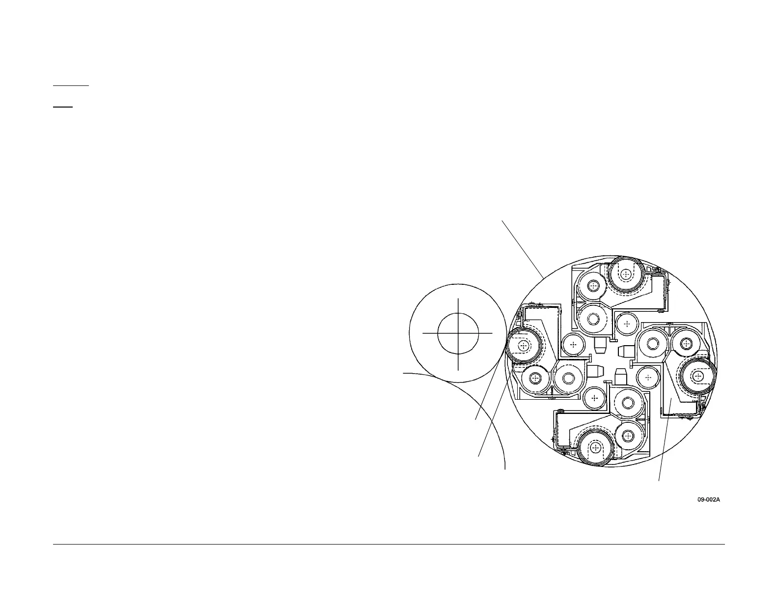
Figure 1 Developer Rotor Assembly
Rotary Assembly
Developer Housing
Assemblies (4)
Development Point
Developer Roll
manuals4you.commanuals4you.com

 Loading...


