1/05
3-11
DocuColor 12/DCCS50
IQ 5 Xerographic Subsystem Checkout Procedure
Image Quality
Reissue
IQ 5 Xerographic Subsystem Checkout Procedure
This procedure is used to isolate Image Quality faults in the Xerographic Subsystem.
Initial Actions
If the problem is density or background related, Perform ADJ 9.1.1 Max Setup. If Max Setup
does not complete successfully, use the Fault Codes that are declared to troubleshoot the
problem.
Procedure
Perform the following Xerographic Hard Stop Procedure:
1. Remove the Paper Handling Module Cover
2. Make sure that the IBT Handle is up.
3. Cheat the Front Door Interlock.
4. Use the Test Pattern that displays the fault.
5. Press Start.
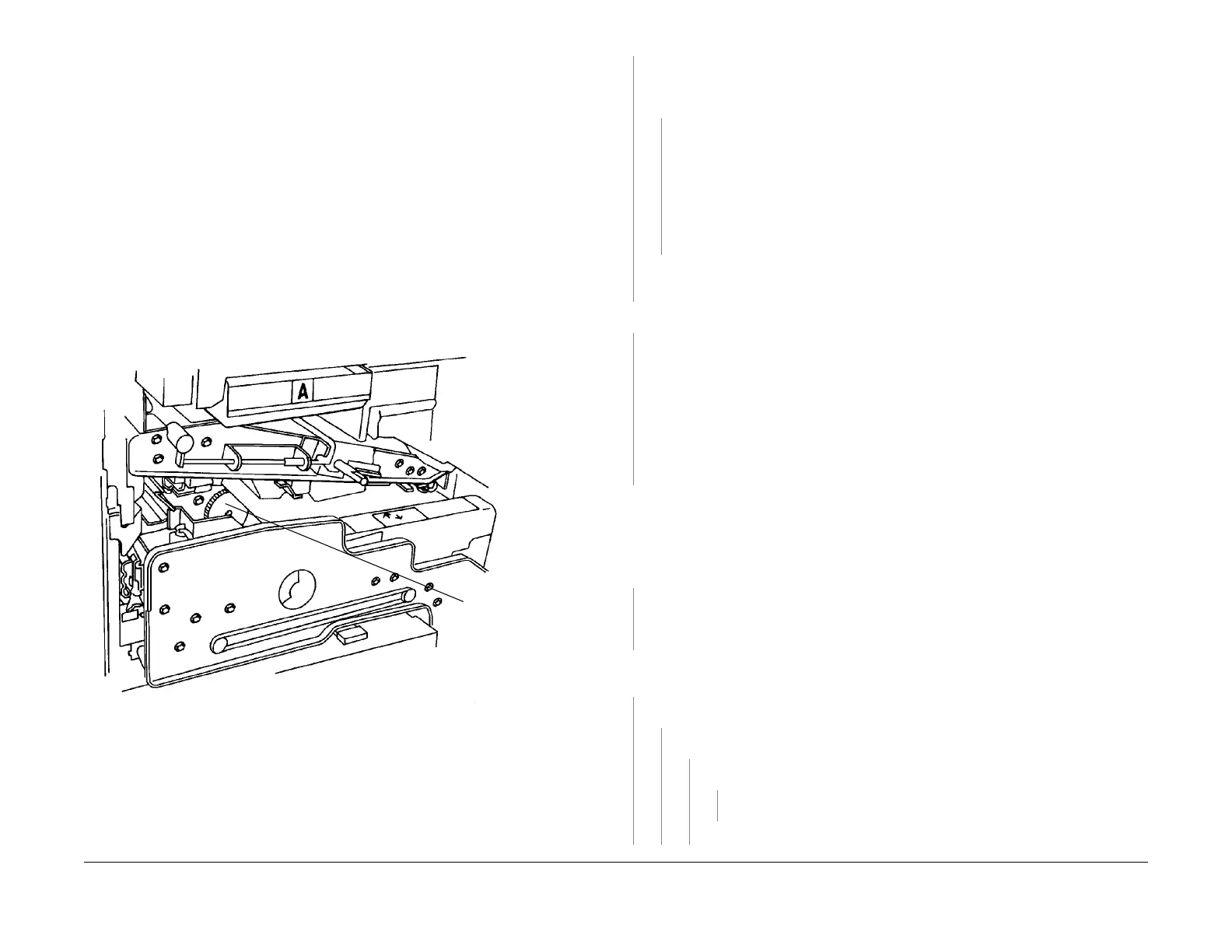
6. Watch the Registration Drive Gear (Figu
re 1).
Figure 1 Registration Drive Gear
7. When the gear starts to rotate, remove the interlock cheater.
8. Extend the Paper Handling Drawer.
9. Remove the two screws that secure the IBT Front Frame and turn IBT handle down.
10. Extend the IBT Drawer to the service position.
Observe the Image on the IBT. The defect is present on the IBT.
YN
The problem is in the IBT, the 2nd BTR, or the Fuser. Repeat the Xerographic Hard Stop
proce
dure.
This time, wait until the paper is on the Vacuum Transport before removing the
interlock cheater. The defect is present on the copy that is on the Vacuum Transport.
YN
The problem is in the Fuser. Disassemble the fuser and carefully inspect the follow-
ing parts for damage or toner buildup.
• Pressure Roll (PL
8.3)
•
Heat Roll Stripper Fingers (PL 8.3)
• Heat Rolls (PL 8.3)
•
Cleaning Roll (PL 8.5)
• Web CRU (Machine Consumables)
Go
to the IQ 40 2nd BTR HVPS RAP.
If the 2nd BTR Power Supply is good, replace the
2nd BTR (PL 9.2). If the problem continues, replace the IBT Belt (PL 7.5).
Repeat the Hard Stop procedure. The defect is present on the Photoreceptor Drum.
YN
The problem is in the 2nd BTR or the IBT. Complete the steps below until the problem is
resolved
• I
f the image defect looks like an ADC Patch Printout
(see Defect Sample 27), check
for the cause(s) of an IBT cleaning problem.
• Go to the IQ 40
2nd BTR HVPS RAP.
• If the 2nd BTR Power Supply is OK, replace the 2nd BTR (PL 9.
2).
• If the problem continues replace the IB
T Belt (PL 7.6).
WARNING
Electrocution Hazard! Do not disconnect the red lead labeled C (Charge Supply Wire).
This wire carries over 8000VDC.
Check the voltage from P/J82-1 on th
e CC/PCC HVPS to frame ground during a copy cycle.
The voltage is between +650 VDC and +750 VDC.
YN
Check the photoreceptor, the corotron wire, and t
he co
rotron grid for defects or damage.
Replace if required (Machine Consumables). If the problem continues, go to the IQ 38
Charge Corotron HVPS RAP.
Check the voltage from P
/J42
2A-7 to frame ground during a copy cycle. The voltage is
between +3.25 VDC and +3.75 VDC.
YN
There is 24 VDC from P
/J141-1 to
P/J141-4 on the ESV Sensor.
YN
There is 24 VDC from P/
J422B-5 to P/
J422B-13 on the IOT Drive PWB.
YN
There is 24 VDC from P/
J411-6
to P/J411-7 on the IOT Drive PWB.
YN
Go to the +
24 V
DC Power (IOT LVPS) RAP.
Replace the IOT Drive PWB (PL 9.
2).
Registration
Drive Gear
A B C

 Loading...


