1/05
6-123
DocuColor 12/DCCS50
dC740 Tray 5 Guide Adjustment, dC915 Machine
General Procedures
Reissue
dC740 Tray 5 Guide Adjustment
Purpose
Checks whether the Tray 5 guide size (width) has been properly detected.
NOTE: For details on adjustment, see ADJ 9.1.
17 Tray 5 Guide Adjustment (dC740).
Procedure
1. Enter the Service Diagnostics Mode. Refer to Entering the Service Diagnostic Mode
using the PWS.
2. Select Adju
stments in the Service Entry Screen.
3. Select Oth
er Adjustments in the Adjustments screen.
4. In the “Other Adjustments” Screen, select and execute the Tray 5 Guide Adjustment
(dC740).
5. Run the guide detection.
a. Set at the minimum position.
i. Set the Tray
5 Guide at the minimum position.
ii. In the “Tray 5 Guide Adjustment Selection” Screen, select Mini
mum Position
and press Start.
iii. If the sensor output is within the range, the system displays OK.
iv. If the sensor output is out of the range, the system displays NG.
b. Set at the maximum position.
i. Set the guide at t
he maximum position.
ii. In the “Tray 5 Guide Adjustment Selection” Screen, select Maximu
m Position
and press Start.
iii. If the sensor output is within the range, the system displays OK.
iv. If the sensor output is out of the range, the system displays NG.
c. Guide test
i. Set the guide at t
he position.
ii. Select and run the G
uide Test in the Tray 5 Guide Adjustment Selection
Screen.
iii. The system displays the detected paper size group in the "Results" (Tray 5
Gui
de Adjustment Selections).
dC915 Machine Output
Purpose
Displays Xerographic information on the Main Processor in an easily seen and understandable
format on the PWS.
1. XERO Related Data Display: Displays all the NVM data related to the Copy Quality as a
set.
2. Displays
the machine NVM data on the PWS UI.
Procedure
Displaying the dC915 XERO Data
1. Enter the Service Diag
nostics Mode. Refer to Entering the Service Diagnostic Mode
using the PWS.
2. Select Adjustmen
ts on the “Service Entry” Screen.
3. Select Machi
ne Output on the “Adjustments” Screen. Machine Data Output Screen is
displayed.
4. Select PWS Di
splay for the “Output Medium.”
5. Select Star
t. “XERO Related Data Display Screen” is displayed.
6. Refer to “XERO Related Chain Link Number List” for the Output Items by the “XERO
Related Dat
a Display” and the details of “XERO Related NVM Data.”
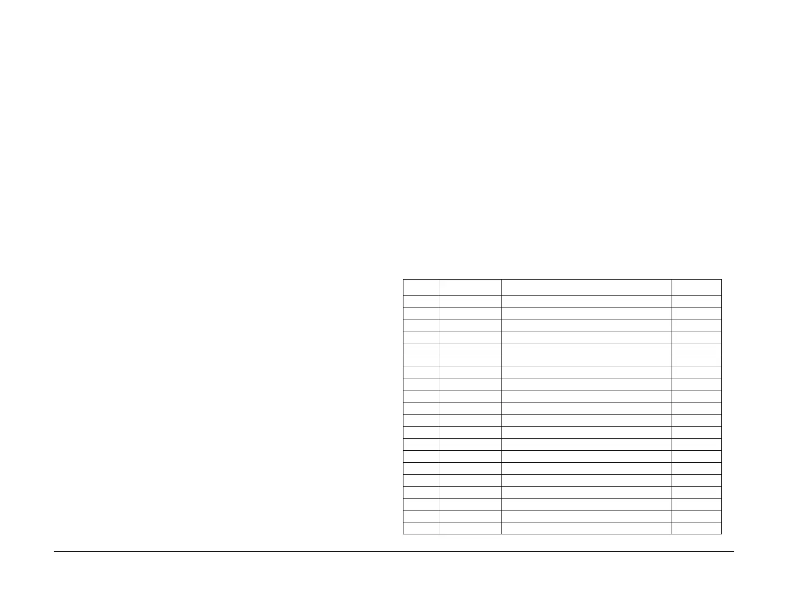
XERO Related Chain Link Number List
Table 1 Xero-related NVM
ID (dec) NVM Number Item Max. (dec)
1 773-028 ADC Vpatch Fault flag 1
2 773-021 ADC Vclean Fault flag 1
3 775-010 Gray-scale ADC Vpatch Fault flag 1
4 775-011 Gray-scale ADC V clean Fault flag 1
5 773-022 VH/VM Fault flag 1
6 773-027 LD CONT Fault flag 1
7 773-099 HUM Fault flag 1
8 773-016 ADC V patch Fault counter: Y 65535
9 773-017 ADC V patch Fault counter: M 65535
10 773-018 ADC V patch Fault counter: C 65535
11 773-019 ADC V patch Fault counter: K 65535
12 773-011 ADC V clean Fault counter 65535
13 775-002 Gray-scale ADC V patch Fault counter: Y 65535
14 775-003 Gray-scale ADC V patch Fault counter: M 65535
15 775-004 Gray-scale ADC V patch Fault counter: C 65535
16 775-005 Gray-scale ADC V patch Fault counter: K 65535
17 775-001 Gray-scale ADC V clean Fault counter 65535
18 773-012 VH/VM Fault counter 65535
19 773-013 LD CONT Fault counter 65535
20 773-014 HUM Fault counter 65535

 Loading...


