1/05
9-37
DocuColor 12/DCCS50
Installation Instructions
Reissue
Electronic Pre-Collation (EPC) Enablement Kit Installation
Purpose
The purpose of this kit is to enable installation of EPC (Electronic Pre-Collation) on machines
without TAG P38. If TAG P38 is already installed Place the Shipping Label on this Kit and
Return it.
Prerequisites
The machine must have the following Tags installed:
• NOTE: Th
e affected machines that require Tag P8 fall within the serial number ranges:
– FU2: 040051 to 040198
– FU3: 310512016x to 310512122x
TAG P8
• TA
G P39 (C
heck that NVM location 752-017 is set to 1).
Kit Contents
The EPC Enablement Kit consists of the following items:
• EPC Scan Cable - qty. 1
• EPC Mounting Plate - qty. 1
• Thumb Nuts- qty. 4
• Connector Bracket - qty. 1
• Harness Assembly - qty. 1
• Connector Cover - qty. 1 (not used)
• Locking Clamp - qty. 1
Procedure
Installing the Scan Cable
1. For DCCS50:
• Switch off the power. Wait 30 seconds, then unplug the power cord. Remove the
IDFE
(REP 19.1).
For DC12 with attached Splash DFE:
• Obtain permission from the network administrator and perform the proper shut down
procedure.
Switch off the Server power. Disconnect the DocuColor 12 interface
cables (print and scan) from the IOT.
• Switch off the machine power. Unplug the power cord.
For DC12 with attached Fiery DFE:
• Obtain permission from the network administrator and perform the proper shut down
procedure.
Switch off the Server power. Disconnect the Copier Interface Cables
(print and scan) from the interface ports on the copier.
• Switch off the machine power. Unplug the power cord.
2. Undock the Finisher or Mailbox/Sorter, if present.
3. Remove the following:
• Exit Tray (PL 12.11)
•
IIT Rear Cover (PL 1
1.3)
• IOT Rear Cover (PL 11.3)
•
Wing Tray (PL 11.1)
, If Present
4. If the Convenience Stapler is not installed: Go t
o, step 11 and continue with the Scan
Cable installation.
If the Convenience Stapler is installed: Continue with t
hese instructions at step 5.
5. Locate and disconnect the stapler power cord.
6. Remove the stapler power cord from the cable anchors (2) on the rear of the machine.
7. Locate and remove the 5.5mm screw securing the green ground wire to the left side of the
machine.
8.
Remove the two 5.5mm screws that secure the stabilizer bracket to the bottom of the Sta-
pler Mounting Cover.
9. Remove the 2 stabilizer bracket screws M4x5.5mm.
10. Remove the Stapler Mounting Cover (PL 16.1
) from the mounting bracket.
11. Open the IIT (REP 3.1.
2)
CAUTION
The VSEL PWB is susceptible to damage from electrostatic discharge Observe all ESD proce-
dures to avoid component damage.
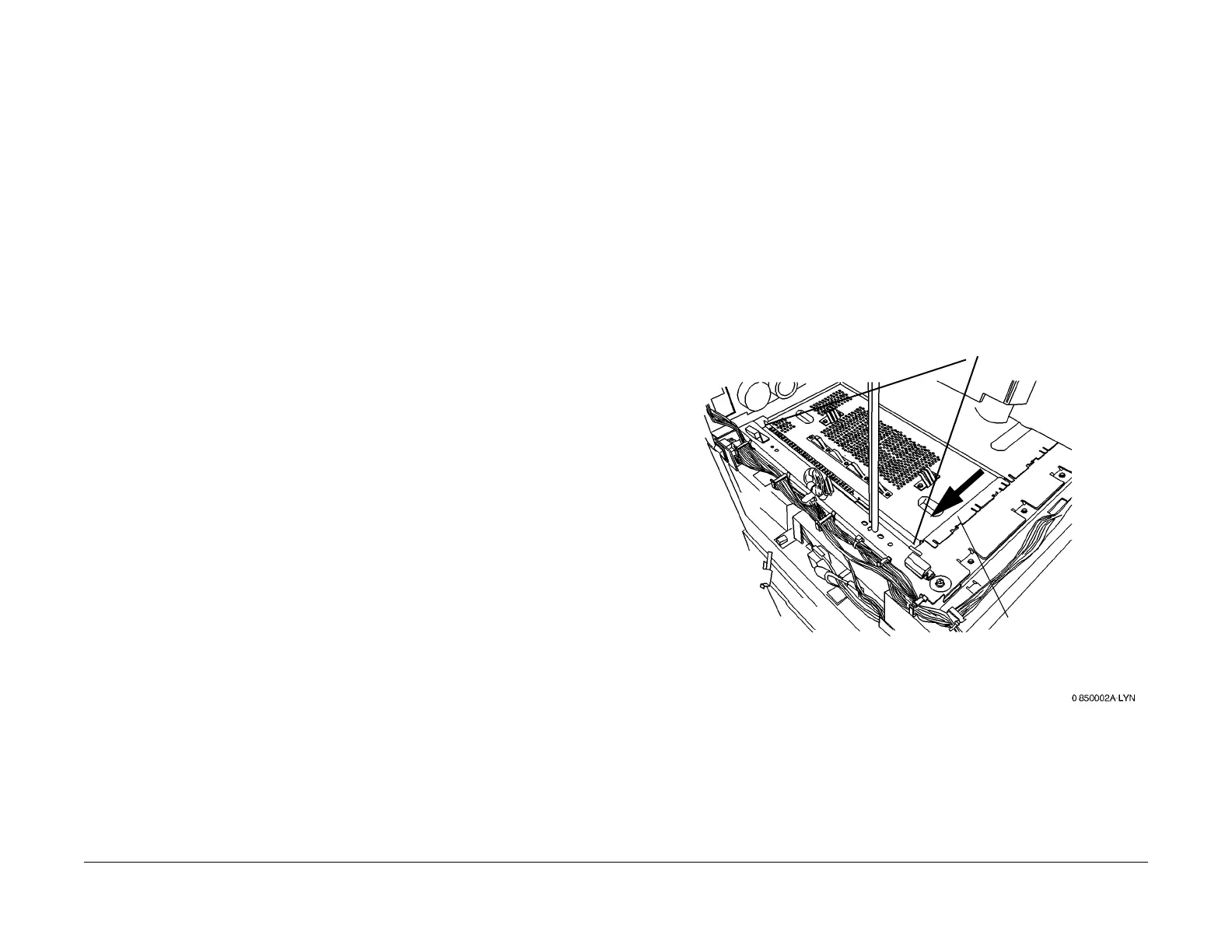
12. Access the VSEL PWB (Figur
e 1):
Figure 1 Accessing the VSEL PWB
1
Remove the screws (2)
2
Remove the Cover

 Loading...


