1/05
10-113
DocuColor 12/DCCS50
Charging
Principles of Operation
Reissue
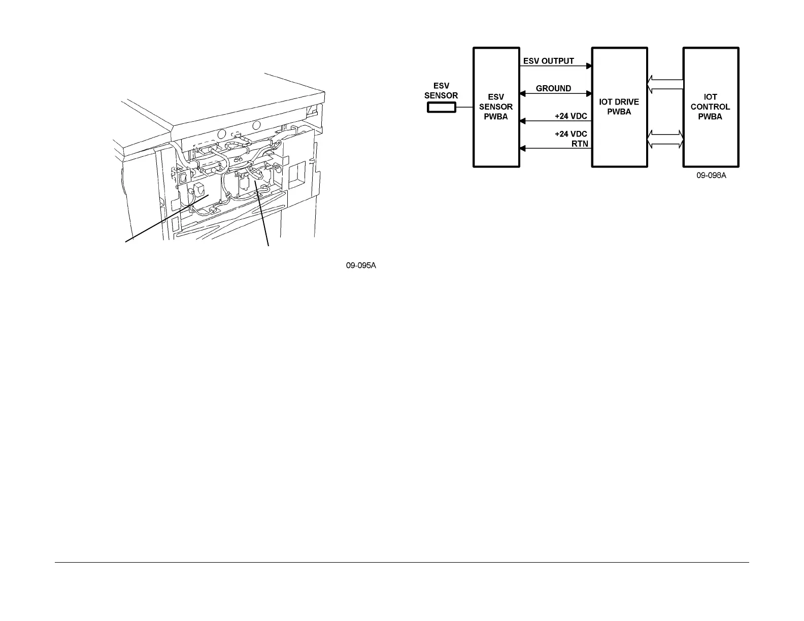
Figure 2 Charge Corotron Grid/Preclean Corotron High Voltage Power Supply (PSHV-L2)
and Developer Bias High Voltage Power Supply (PSHV-L1) Location (09-095)
Charge Corotron Cleaning
The Charge Corotron is not cleaned. It is part of t
he Photoreceptor Drum CRU, or can be
changed by a service engineer (ERU).
ESV
The Electrostatic Voltmeter (ESV) consists of an ESV Sensor and an ESV PWBA. The ESV
Sensor produces
an output which is proportional to the drum surface potential. The ESV
PWBA processes this output and provides a signal to the IOT Drive and Control PWBAs. This
output is a scaled representation of the drum surface potential and has a range of 0 - 4.9 VDC.
Figure 3 ESV circuit
Charge Corotron HVPS
The CC/PCC-HVPS (HVPS-L2) provides a regulated constant
current to the Charge Corotron.
This is typically in the range of 630 to 770 microamperes. To accomplish this, the power supply
charges the Charge Corotron to -300 to -1000 VDC. The output current and voltage are con-
trolled by Pulse Width Modulator (PWM) control signals from the IOT Drive and Control
PW
BA
s. Interlocked +24 VDC from the IOT Drive PWBA is the power input from which the high
voltage output is generated.
CC/PCC HIGH VOLTAGE
POWER SUPPLY (PSHV-L2)
DEVELOPER BIAS HIGH VOLTAGE
POWER SUPPLY (PSHV-L1)

 Loading...


