1/05
10-140
DocuColor 12/DCCS50
Functional Description of Fuser Subassemblies
Reissue
Principles of Operation
The IOT Control and Drive PWBAs manage power to the three heated rolls to reduce maxi-
mum energy usage within the machine. The energizing cycles vary, depending upon the
machi
nes operating status (warm-up, stand-by or running) and the type of copy job running
through the machine (standard weight, heavy weight, or larger quantities of copies to run). At
no time during the copy run cycle are the Heat Roll and Pressure Roll energized for heat at the
same time.
Each roll’s temperature is read by the IOT Drive and Control PWBAs every 500ms. Power to
t
he
rolls is changed only after ten consecutive readings.
Fuser Warm Up Sequence
Warm up time for the Digital Copier is about 7.5 minutes. W
arm up time for the Copier/Printer is
about 8 minutes, and for the Printer, about 9.5 minutes.
The temperature control and sequence for Fuser warm up is a four stage process. Refer to
Table 5 fo
r this sequence.
The user is given a ready indication when the Heat Roll reaches 160° and the Pr
ocess Control
Setup routines are complete.
Fuser Cooling System
The Fuser has an air circulation system to prevent excess heat build up in the machine. This
system
consists of:
• Fuser Intake Fan
• Fuser Duct
• Fuser Exhaust Fan
The Fuser Intake Fan is mounted on the front door of the machine. This fan draws room air into
the
Fuser Duct, which is attached to the top of the Fuser Assembly. The Fuser Duct has metal
panel on its bottom which absorbs the radiant heat generated by the Fuser. The circulating air
in the duct passes over this metal panel and draws this heat out of the machine as the air exits
through the Fuser Exhaust Fan on the right side of the machine.
Camming of Rollers
There are two rolls in the Fuser that use camming action:
• Pressure Rol
l - Cams up to contact the Heat Roll to create the Fuser nip (Contact Arc)
for the copy fusing process.
• External Heat Roll - Cams
down to contact the Heat Roll to provide supplemental heat-
ing to the surface of the Heat Roll.
When the External Heat Roll and the Pressure Roll are cammed away from the Heat Roll, there
is a 3 mm
gap between the Heat Roll and the other two rollers.
PR/HR Nip (Pressure Roll Camming)
The IOT Control PWBA creates a PR/HR nip by engaging the Fuser Nip Clutch and the Exit
Motor
. This combination rotates a shaft with an eccentric cam attached that forces the Pres-
sure Roll up into the Heat Roll.
Two factors combine to determine when this nip is created. The first factor is the TR0 pulse
which star
ts movement of blank print media from a tray. The second factor is delay interval
stored in the IOT NVM. This is shown as B in Figure 4 and Figure 5. There are actually 7 inter-
vals stored in the IOT NVM. Which
one
is used depends on three factors:
• The type of blank media being used.
• The thickness of the blank media being used
• Whether the job is color or B & W
• Whether the Fixing Surface is on the top or bottom.
Default values of interval B range from 01 seconds for B & W jobs on normal paper and trans-
parency material to 10 seconds for color jobs on extremely heavyweight paper.
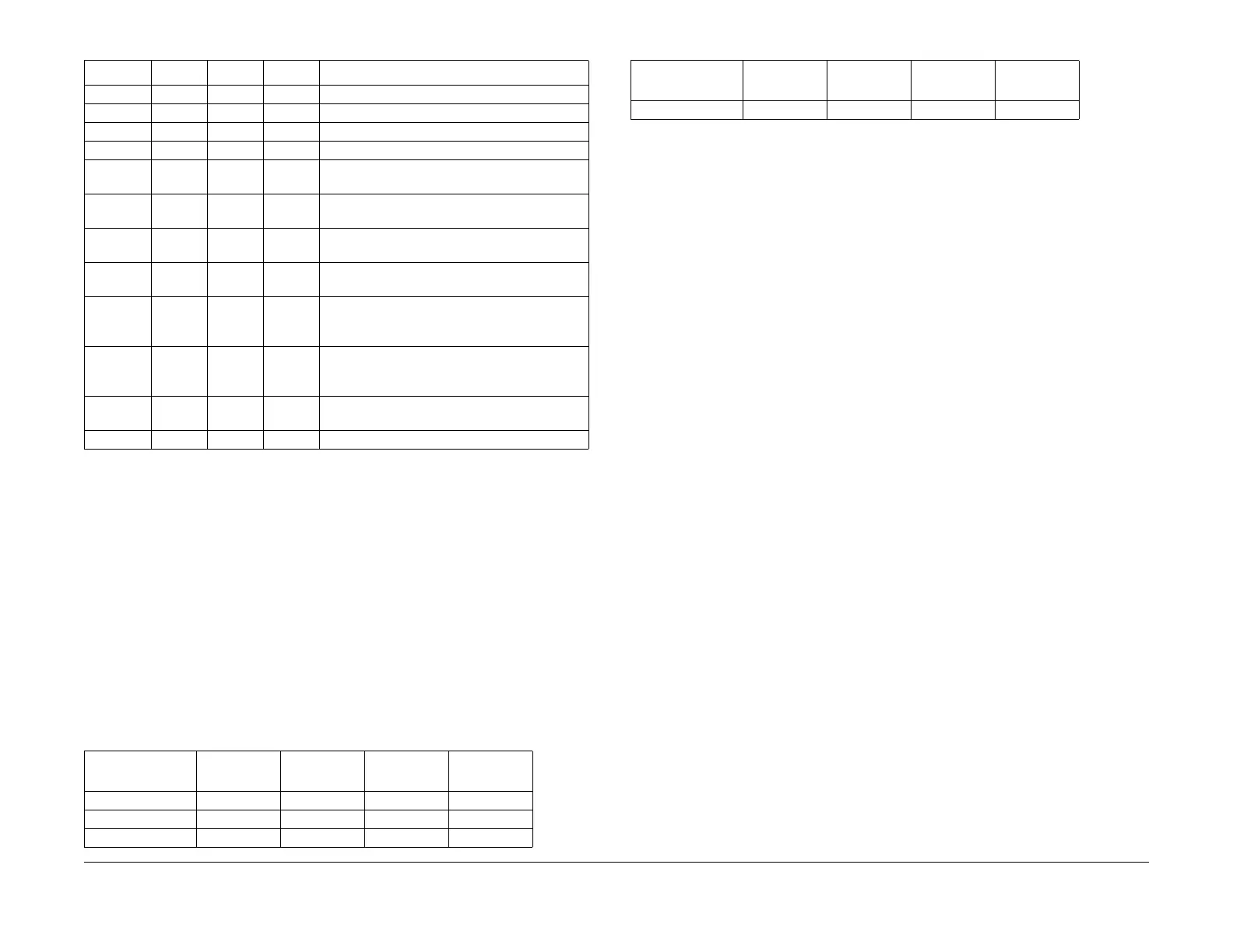
13 110 115 150 PR Ready Floor Temperature
14 180 185 200 EHR Ready Floor Temperature
15 140 155 170 HR Nip Width Adjustment Floor Temperature
16 100 115 130 PR Nip Width Adjustment Floor Temperature
17 150 170 190 EHR Nip Width Adjustment Allowed Tempera-
ture
18 160 195 220 EHR Secondary Control Temperature when
u
sing nor
mal paper for 4-color
19 160 210 220 EHR Secondary Control Temperature when
using nor
mal paper for B&W
20 160 210 220 EHR Secondary Control Temperature when
using O
HP material for B&W
21 160 190 220 EHR Secondary Control Temperature when
using O
HP material or heavyweight or very
heavyweight paper for 4-color
22 160 190 220 EHR Secondary Control Temperature when
u
sing heav
yweight or very heavyweight paper
for B & W
24 155 165 170 EHR temperature Control Determination Tem-
perature
22 10 20 30 PR Post-Job Temperature Difference
Table 5 Fuser Warm up Sequence
Step 1:
P
ower
On
Step 2:
Initialize
Step3: Fuser
Drive
Step 4:
Fuser Ready
H/R Lamp 630W 630W 481W 379W
P/R Lamp 350W 350W 350W 350W
Ext H/R Lamp 62W 218W 340W 340W
Table 4 IOT Control NVM Fuser Roller Temperature Entries
Tem
p No. Min Nominal Max Description
Fuser Motor off off on on
Table 5 Fuser Warm up Sequence
Step
1:
Power On
Step 2:
Initialize
Step3: Fuser
Drive
Step 4:
Fuser Ready
manuals4you.commanuals4you.com

 Loading...


