1/05
10-129
DocuColor 12/DCCS50
Cleaning Systems, Air Flow
Principles of Operation
Reissue
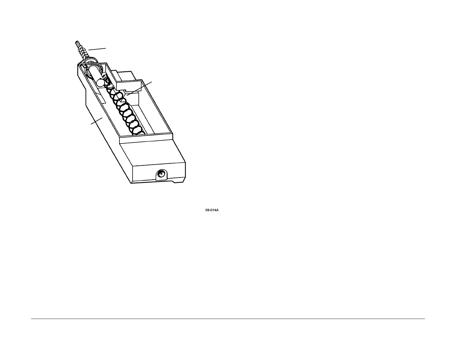
Figure 3 Waste Toner Bottle and Associated Augers
Air Flow
The air flow system used in this machine performs the following functions:
• Eliminates the toner and dust particles that float around inside the machine
• Discharges the ozone generated by the Corotrons
• Provides machine cooling
• Provides suction for paper transport
There are a total of five fans used to vent or cool var
ious
parts of the machine. In addition to the
fans, this system consists of ducts to channel the air flow, filters to collect particle contaminants
and safety interlock switches. In general, the air is drawn into the machine from the front and it
exits the back. The five fans in this machine are:
• Charge Corotron Intake Fan
• Fuser Intake Fan
• Fuser Exhaust Fan
• Suction Blow
• IIT Fan (See Imaging)
Charge Corotron Intake Fan
The located on the inside of the front door, closest to the door hinge. It draws the room air into
the machine, directing it through a filter that is attached to the Waste Toner Bottle and into the
Charge Corotron Duct system. This Duct system for the Photoreceptor Drum draws the ozone
away from both the Charge Corotron and the Preclean Corotron. A duct is also around the Seal
Roll to extract any stray toner residue prior to the Drum transferring the developed image to the
IBT.
Fuser Intake and Exhaust Fans
Two fans remove heat generated by the three heated rollers of the Fuser Assembly. The Fuser
Intake Fan is located on the inside of the front door, furthest away from the hinge. It draws room
air into the Fuser Duct system. The Fuser Exhaust Fan is located by the top right side of the
machine, at the exit side of the Fuser Duct System. The Fuser Duct sits above the Fuser
Assembly drawing the radiant heat generated by the Fuser away from the other components
within the machine.
Suction Blower
The Suction Blower is located on the bottom, right side of the back of machine. It is a 24 VDC
fan that draws the air out of the machine, taking the air from the ducts for the Photoreceptor
Drum and the Vacuum Transport. The duct before this fan contains a three part ozone and dust
filter.
Air System Electrical Control
As shown in Figure 1, the Fuser Fan is powered by unswitched +12 VDC directly from the AC
Driver PWBA. Therefore, anytime that the machine is plugged in and the machine circuit
breaker is closed, the fan is running. The FAN HI/LO speed control originates from the IOT
Drive PWBA and is routed to through the AC Driver PWBA.
WASTE TONER
BOTTLE AUGER
COIL AUGER
WASTE TONER
BOTTLE

 Loading...


