1/05
10-149
DocuColor 12/DCCS50
Mailbox/Sorter Interlocks
Principles of Operation
Reissue
Mailbox/Sorter Interlocks
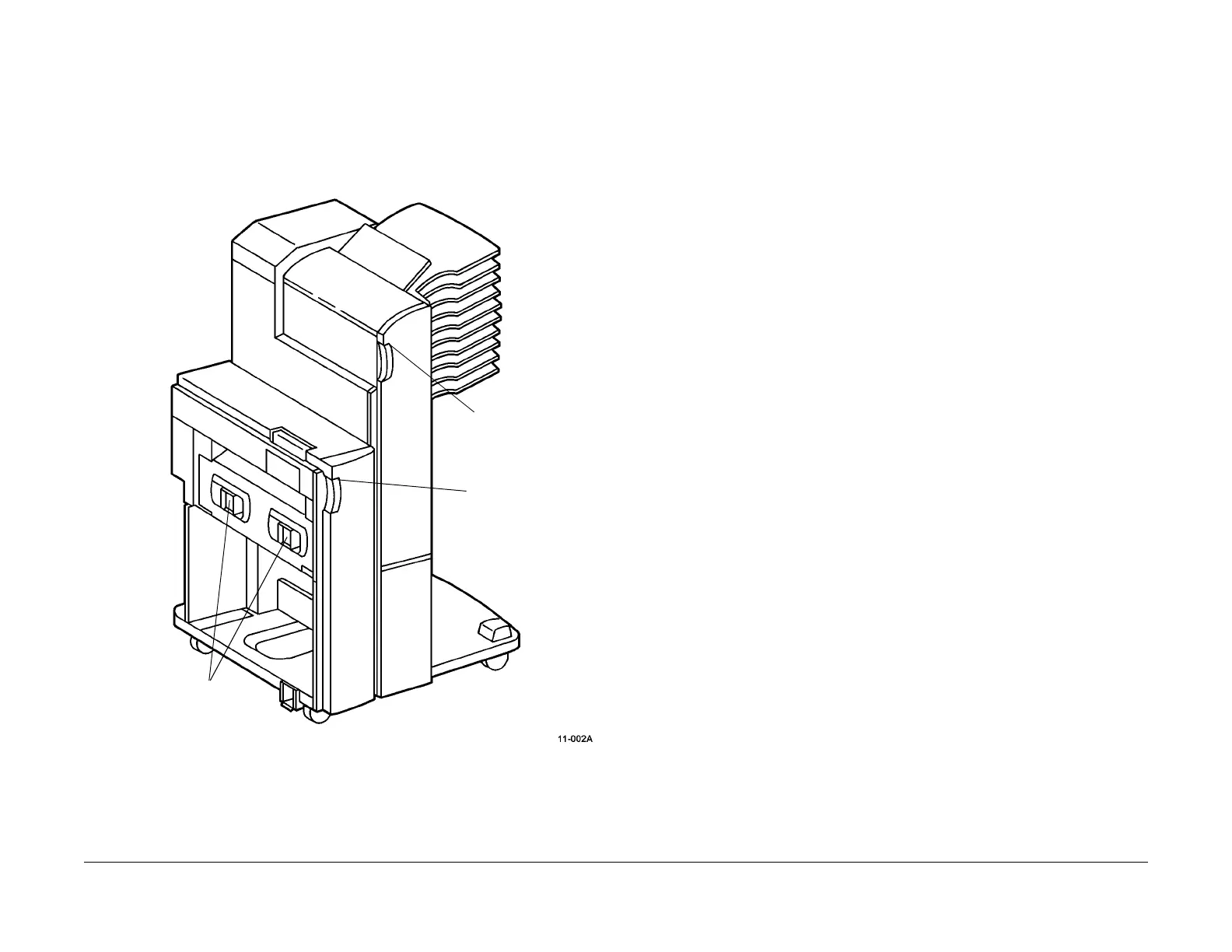
The Mailbox/Sorter has four (4) pairs of interlock switches:
• Two Docking Interlocks that detect when the Decurler is connected to the basic machine.
• Decurler Front Cover Interlock
• Mailbox/Sorter Front Cover Interlock
Figure 1 Interlock Switch locations for the Mailbox/Sorter
The Decurler Front Cover Interlock is actually two switches. When the cover is off, one pole of
t
his
switch disconnects +24 VDC supply voltage from the Decurler Stepper Motor. The other
switch and all of the remaining interlock outputs are all normally at +5 VDC, but are grounded
when opened. The microcontroller on the Mailbox/Sorter Control PWBA reads the voltage sig-
nals. An open interlock causes the microcontroller to send a message to the IOT CPU PWBA,
inf
orm
ing it of the interlock condition. An appropriate message displays on the machine User
Interface.
Sorter Front Cover
Interlock
Decurler Front Cover
Interlock
Docking Interlocks (2)

 Loading...


