1/05
6-26
DocuColor 12/DCCS50
dC129 System Registration Adjustment, dC131 NVM
Reissue
General Procedures
dC129 System Registration Adjustment
Purpose
Performs the Lead Registration and Side Registration Adjustments by looking at the output of
the built-in Test Pattern for adjustment.
NOTE: For details on the dC129 System Registration adjustment, see ADJ 9.
1.10: IOT Side/
Lead Edge Registration (dC129: System Registration Adjustment).
Procedure
1. Enter the Service Diagnostics Mode. Refer to Entering the Service Diagnostic Mode
using the PWS.
2. Select the Adjustmen
ts Tab on the Service Entry Screen.
3. Select Othe
r Adjustments Tab on the Adjustment/Setup Screen. The System Registra-
tion Adjustment Screen is displayed.
4. Specify the Tray at
the Tray/Size pull-down and the number of copies at the Print Count
Window.
NOTE: Tray1 is the default Tray and cannot be changed to another Tray from the PWS.
NOTE: Number of copies can be set between 1-99.
NOTE: Selecting Prin
t All will print a test pattern from each tray.
5. Select Print A
ll. The message, executing System Registration Setup (dc129) is dis-
played.
6. The specified number of built-in patterns is output
and the message, “Completed” is dis-
played in the status area.
a. The message screen informing that the Main Processor is, “abnormal” will be dis-
played if Test Copy of the built-in pattern cannot be executed.
7. Add/Subtract the Registration Adjustment Value by looking at the copy. Using the arrows
f
or the “Lead Reg” and “Side Reg”, adjust the Lead and Side Registrations:
a. Lead Reg.
1step (click) =.1100mm. Maximum steps (clicks) = 100
b. Side Reg.
1step (click) = 0.0423mm. Maximum steps (clicks) = 300
8. Select Set A
djust Value after confirming the Registration Adjustment Value.
a. “Current NVM Value” of the Lead Registration/Side Registration are renewed when
this,
“Set Adjust Value” and “Save (LR)” is selected. Restore (LR) and Restore (SR)
buttons will restore the “Current NVM Value” to the initial value.
b. “NVM Value at Save” is displayed. This display will be changed when S
ave (LR) or
Save (S
R) is selected again.
c. Save (LR)
, Save (SR) will save “LR” or “SR” NVM in “NVM Value at Save”.
9. The message, “In Progress” is displayed.
a. When the machine cannot change the NVM value, the message, “! Unable to set up
adjustment
value. Cancel Adjustment Value Setup” is displayed on the Information
screen.
10. Verify the adjustment by printing another pattern.
11. If the pattern does not meet Image Quality requirements, repeat steps 8-11 of this adjust-
ment procedure.
dC131 NVM Read/Write
Purpose
Reads, sets or changes the NVM data.
NOTE: You can access all NVMs including the NVM for a key operator. The billing forgery pre-
vention function and the auditron administration password cannot be overwritten.
Procedure
Module Selection
1. Enter the Service Diag
nostics Mode. Refer to Entering the Service Diagnostic Mode
using the PWS.
2. Select Adjustmen
ts in the Service Entry Screen.
3. The system displays one of the Read/Write Screens. dC131 NVM Read/Write is the
default
screen.
4. Select a Sub
-System from the Vertical Left Tab List. The default tab is ‘All’.
Reading NVM
1. Select an ID f
rom
the Sub-System Table, then click Read NVM or double click on the line
ID (line) and the value will be read in the value column. The "Range Check" column will fill
in.
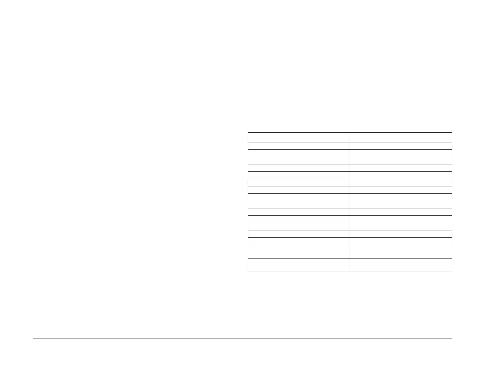
Table 1 Module Selection
Module item Chain number allocation
All 700 - 999
UI/Tools 700,702
IISS 715
Config 719
ROS 720
IPS 730
PHM 740, 749, 760, 761
System 752, 759
Xero 771, 774
Drives / Output 772, 780, 790
ProCon 773
Developer 776
Fuser 777
Other 775, 800, 850
Errors (number of errors) Displays and NVM outside of the ranges listed
in
the PW
S database.
Changed (number pending change) Displays any with new value entered in the
"New" col
umn, but not written yet.
manuals4you.commanuals4you.com

 Loading...


