1/05
10-120
DocuColor 12/DCCS50
Development
Reissue
Principles of Operation
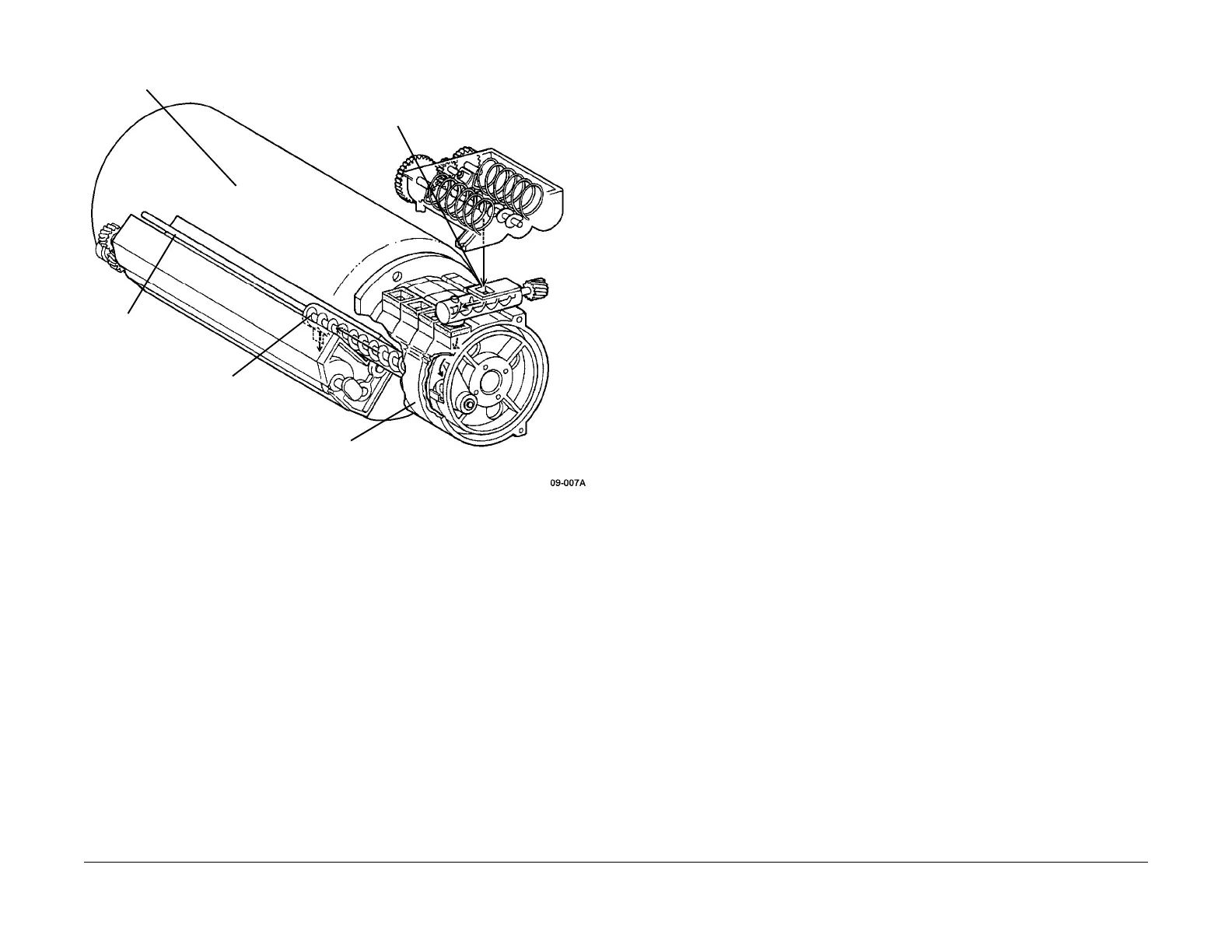
Figure 7 Rotary Dispenser and Developer Housing Assembly (Example)
Trickle System
This machine uses a “Trickle System” for replenishing the developer.
This system increases the
usable life of the Developer Assemblies. It includes the following:
• New developer (toner plus carrier beads) is supplied to the
Developer Housings by the
Toner Supply system.
• Used carrier beads from the Developer Roll are remixed back in with the new developer at
the Developer
Housing.
• Any excess waste carrier beads that accumulates in the Developer Housing is discharged
into a ce
ntral Waste Auger and transported to the Waste Carrier Bottle. This Waste Auger
and Waste Carrier Bottle accepts the excess developer from all four colors.
This system starts with the Toner Cartridges which carry a mixture of both toner and carrier
beads.
The di
fferent colors of developer are transported to the appropriate Developer Housing
within the Developer Rotary Assembly. When the latent image on the Photoreceptor Drum is
developed, the toner is electrostatically attracted to the drum and the metal carrier beads
remain on the magnetic Developer Roll.
The carrier beads are brought back into the Developer
Housing and remi
xed with the existing
developer. New developer is added to the Developer Housing (see Toner Supply) at a rate
determined by readings taken from the ADC patch on the Photoreceptor Drum.
Excess waste carrier beads for each Developer Housing are tr
ickled out automatically through
a shutter gate into a center Waste Auger when the Developer Housing is at 90° above the
development point.
When performing black only copying, the black Dev
eloper Housing needs t
o rotate up to the
90° location to remove the depleted waste carrier beads into the center Waste Auger. This is
done when:
• The copy job is completed
• The Toner Dispense Motor runs continuously for 17 seconds.
Waste Carrier Bottle
The Waste Carrier Bottle receives the waste developer fr
om all four Developer Housings. A
magnetic sensor is used to detect a full Waste Carrier Bottle. The sensor is monitored once
every second. When the waste carrier full status is detected by the sensor five times in succes-
sion, then a “caution” notice (09-423) for the status of
th
is bottle is sent to the User Interface
screen.
The machine monitors both the sensor status and the
rotating time of the Toner Dispense
Motor from this caution status. When a specific accumulated NVM value for the Toner Dis-
pense Motor is reached, then a Waste Carrier Bottle f
ail signal (09-379) is s
ent to the User
Interface.
Toner Supply Control
Toner supply is controlled by the IOT CPU P
WBA, through the IOT Drive and Dispense
PWBAs. The Low Toner Sensor output is routed to an input port on the IOT Drive PWBA,
where it can be read by the CPU on the IOT CPU PWBA. Likewise, the CPU controls a port
output from the IOT Drive PWBA for both the Cartridge and Dispense Motor control lines.
These control lines enable Dispense PWBA circuitry which converts Interlock +24 VDC to 24
VAC, 60 Hz power for the motors. Note that in Figure 9, only the black control and status lines
are shown. The yellow, magenta and cyan circuitry is exactly the same.
DEVELOPER ROTARY
ASSEMBLY
AXEL SHAFT
ROTARY
AUGER
DEVELOPER INLET
ROTARY
DISPENSER
manuals4you.commanuals4you.com

 Loading...


