1/05
10-139
DocuColor 12/DCCS50
Functional Description of Fuser Subassemblies
Principles of Operation
Reissue
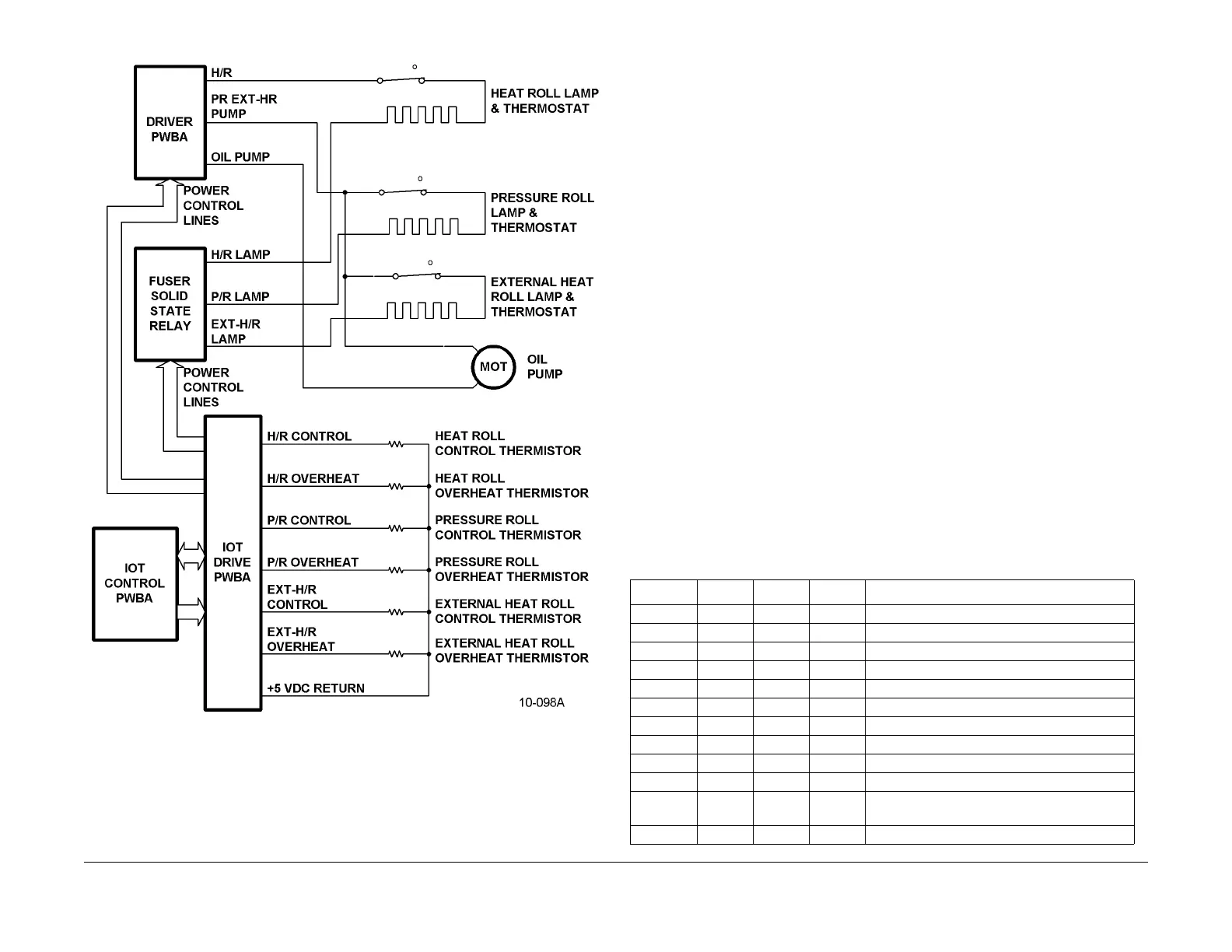
Figure 2 Fuser Heaters and Heater Control Block Diagram
All aspects of Fuser operation, including its temperature, are cont
rolled by the IOT Control and
Drive PWBAs. At the highest level, the Fuser has two operating states:
• Fuser Ready - The HR, PR and EHR have all reached their Ready Temperatures. (See
Table 4.)
•
Fuser Not Ready - At least one of the HR, PR and/or EHR is below its Not Ready Temper-
ature. (See Table 4.)
The Fuser Ready state can be divided into two substates:
• Standby - The Fuser Motor isn’t running.
• Run - The Fuser Motor is running.
The Fuser Not Ready state can be divided into three substates:
• Preheat - The Fuser lamps are heating the rolls to their Preheat Temperatures. (See Table
4.
) T
hese temperatures are below the Ready Temperatures. This is done as a means of
reducing First Copy Out time.
• Warm-up - The Fuser lamps are heating the rolls to their Ready Temperatures.
• Stop - All Fuser lamps are shut off due to a paper jam, a machine failure has occurred or
a machine
interlock is open.
• Heat Roll Empty Rotation - When printing small copy media sizes, heat will be transferred
to
the media from isolated parts of the Heat Roll. Over time, this may cause the tempera-
ture of the HR surface to become uneven. Theref
ore, under
certain conditions, the Fuser
will perform a Empty Rotation Operation for approximately 40 seconds. This allows the
EHR to make the HR surface temperature more uniform. This only occurs if the HR tem-
perature is above the HR Empty Rotation Operation Floor Temperature.
• Primary and Secondary Control Temperatures - Cont
ro
l temperatures are the tempera-
tures that the IOT Control PWBA attempts to maintain during Fuser Run. Each of the rolls
has both P
rimary and Secondary Control Temperatures. Primary temperatures are the
starting target temperatures. Secondary Control Temperatures are calculated values
which depend on the NVM values shown in Table 4 and the difference between maximum
and minimum temperatures measured in ten consecutive samples (Table 5). If the tem-
perature difference is small enough, then the heat
lamp can be swit
ched on less often
than normal, and the Secondary Control Temperatures can be used. This reduces the
likelihood of the roll temperature will overshoot its maximum temperature after a job
because its heating lamp is unnecessarily switched on immediately before the end of the
job.
Table 4 IOT Control NVM Fuser Roller Temperature Entries
Temp No. Min Nominal Max Description
1 130 160 200 HR Primary Control Temperature
2 70 120 180 PR Primary Control Temperature
3 160 190 220 EHR Control Temperature (Primary)
4 PR Not Ready Temperature; Formula-based
5 100 115 180 PR Secondary Control Temperature
6 HR Not Ready Temperature; Formula-based
7 100 150 180 EHR Not Ready Ceiling Temperature
8 100 130 150 HR Preheat Temperature
9 80 100 150 PR Preheat Temperature
10 100 120 150 EHR Preheat Temperature
11 100 140 160 HR Empty Rotation Operation Floor Tempera-
ture
12 150 155 170 HR Ready Floor Temperature

 Loading...


