1/05
10-137
DocuColor 12/DCCS50
Functional Description of Fuser Subassemblies
Principles of Operation
Reissue
The Pressure Roller Cam is a clutch-driven shaft with cams on each end. When rotated, it
raises and lowers the Pressure Roller. Attached to the shaft is a flag that passes through an
optical sensor. The sensor is blocked by the flag and indicates the Pressure Roller is cammed
up and in contact with the Heat Roller. The normal position of the Pressure Roll is away from
the Heat Roll when the fusing process is not required. For the 220 mm/sec. transport speed),
the Pressure Roll remains in contact with the Heat Roll during the print run. For the 130 mm/
sec and 60 mm/sec transport speeds, the Pressure Roll cams away from the Heat Roll
between copies within a print run.
The Retract Motor rotates an eccentric cam shaft that is used to raise and lower the External
Heat
Roll
against the Heat Roll. A flag on the end of this shaft actuates an optical sensor to sig-
nal that the External Heat Roll is in the correct position. See “Camming of Rollers” section for
m
or
e details.
The Web Motor drives the Take-up Roll on the Web Assembly. This motor pulls the Web mate-
rial across the Heat Roll and Cleaning Roll. Refer to the W
eb Cleaning of t
he Heat Roll for
more information on the Web subassembly.
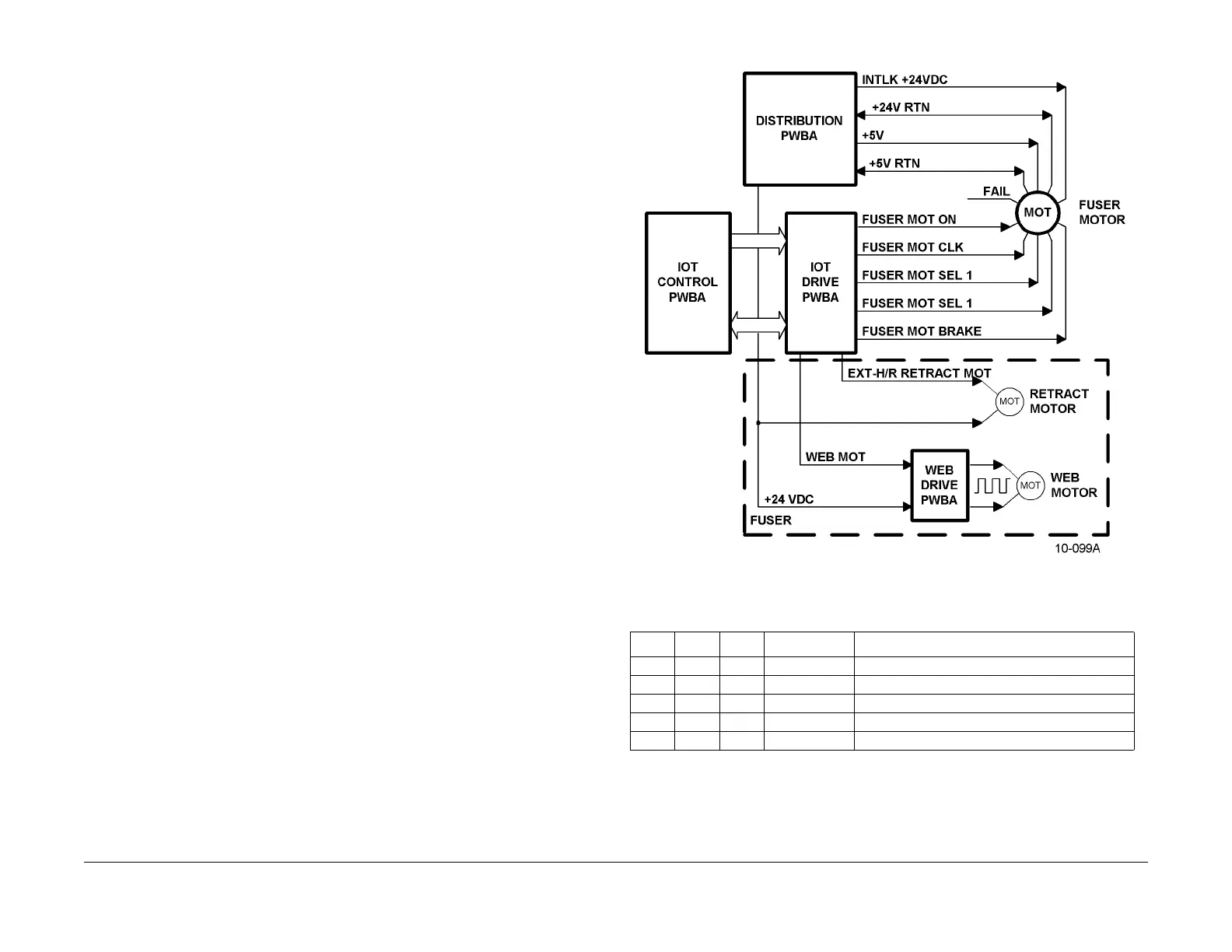
Figure 1 Fuser Motors Electrical Block Diagram
Table 2 Fuser Motor Control Lines and Condition
On Sel 1 Sel 2 CLK Fuser Motor Operating Condition
0 X X N/A Motor Off
1 0 0 545.37 Hz 59.82 mm/sec process speed
1 0 1 N/A Not used
1 1 0 1182.31 Hz 130 mm/sec process speed
1 1 1 2000.8 Hz 219.47 mm/sec process speed

 Loading...


