1/05
10-121
DocuColor 12/DCCS50
Development
Principles of Operation
Reissue
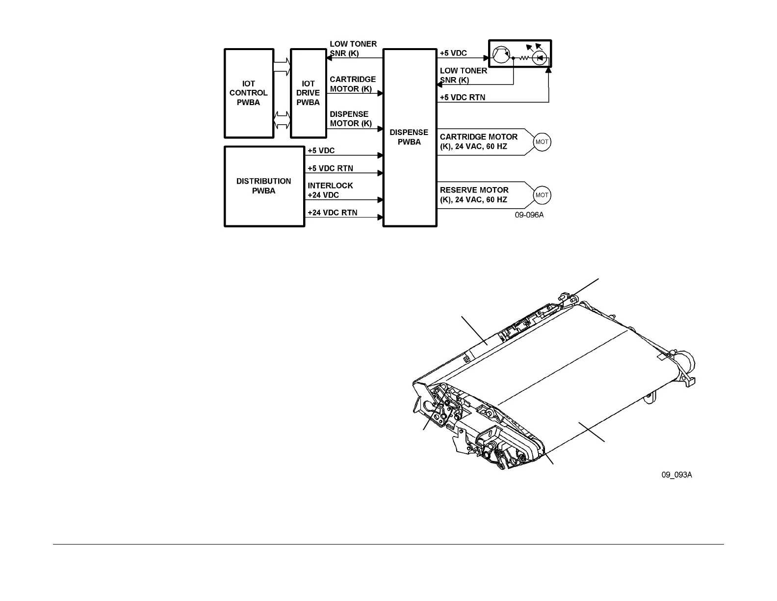
Figure 8 Toner Supply Control Simplified Block Diagram (Black)
ADC (Automatic Density Control)
The ADC Sensor is a Polarized Color Densitometer (PcDM) consisting of a Light Emitting
Diode (LED), a phototransistor and a polarizing filter. The ADC Sensor is located in the IBT
Assembly. This sensor reads the reflected light from a toner patch placed on the IBT Belt. This
reflective reading is used by Process Controls to determine the density level of the image
which will then determine the required running times for toner dispensing.
The current through the phototransistor is proportional to the amount of light reflected from the
developed p
at
ch. The current is converted to a voltage level on the ADC Sensor PWB and that
voltage signal is sent as two analog signals through IOT Drive PWB to the IOT CPU PWBA
where it is used for process control functionality. The ADC Sensor and ADC Sensor PWB are
part of the ADC Sensor Assembly. Refer to Figure 10 for a block diagram of the ADC Sensor
control.
Figure 9 IBT and Selected Subassemblies Locations
ADC patches are made and read:
ADC SENSOR
TR0 SENSOR
IBT BELT
DRIVE ROLL (INSIDE
BELT)
STEERING
ROLL
(INSIDE
BELT)

 Loading...


