1/05
10-29
DocuColor 12/DCCS50
User Interface Base PWBA
Principles of Operation
Reissue
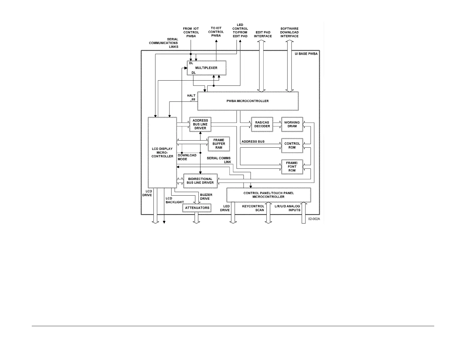
Figure 1 User Interface Base PWBA Block Diagram
The PWBA Microcontroller and Display Microcontroller share DRAM and ROM. (Both micro-
controllers also include on board RAM and ROM.) The PWBA Microcontroller disables the LCD
Display Microco
ntroller whenever it must access that memory. The PWBA Microcontroller also
multiplexes the communications links with the IOT CPU PWBA and Edit Pad LED Control
between itself and the LCD Display PWBA. It also provides separate communications inter-
faces with the Edit Pad and the Portable Workstation (PWS). The PWS is used to download
s
oftw
are into the UI Base PWBA.
The LCD Display Microcontroller uses the data in the F
rame Buffer RAM to drive the display on
the LCD Display PWBA. The LCD Display Microcontroller also outputs drive signals to the
buzzer located on the Push-button/LED PWBA. These outputs are routed through individual
attenuators, each of which has a different value of attenuation. This permits the buzzer to have
three different volume levels and an almost infinite number of tones.
The Control Panel/Touch Panel Microcontroller det
ect
s changes in the status of the push-but-
ton using seven row lines and four column lines. I
t also drives the LEDs on the Key/LED
PWBA, and connects with the Left, Right, Up and Down analog input/outputs from the Analog
Touch Panel.

 Loading...


