1/05
10-125
DocuColor 12/DCCS50
IBT Assembly
Principles of Operation
Reissue
TR0 Sensor
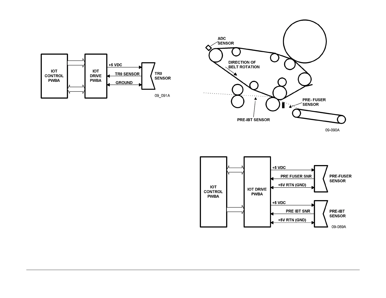
As shown in Figure 10 and Figure 3, the TR0 Sensor is mounted on the back left side of the
IBT Frame Assembly. This sensor monitors two TR0 patches on the IBT to monitor cycle
speed. As shown in Figure 4, the sensor output goes to the IOT Drive and Control PWBAs.
There, it forms the basis for synchronizing all paper transport activities.
Figure 3 TR0 Circuit Block Diagram
IBT/Media Transport Sensors
There are two sensors to detect IBT paper jams.
• The Pre-IBT Sensor monitors for paper jams between the Registration Roll and the 2nd
BTR. Loca
ted on the 2nd BTR Inlet Chute.
• The Pre-Fuser Sensor detects the print as it r
eaches the Vacuum Transport. An abnormal
indication is that the leading edge of the print is not detected by this sensor within approx-
imately 400 msec (at 220 mm/sec. process speed) af
te
r the 2nd IBT Sensor detects the
same edge. Located in the 2nd BTR Exit Chute.
Figure 4 IBT/Media Transport Sensor Locations
Figure 5 Partial electrical schematic for IBT Sensors
In addition to the paper jam sensors for the IBT, there is the ADC (Autom
atic Density Control)
Sensor and the TR0 Sensor. Refer to these sections for more information on these two sen-
sors.

 Loading...


