1/05
10-141
DocuColor 12/DCCS50
Functional Description of Fuser Subassemblies
Principles of Operation
Reissue
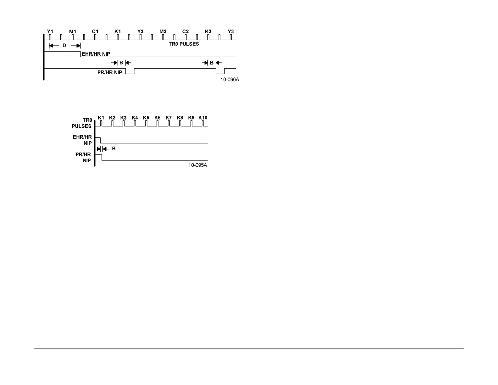
Figure 3 Fuser Nip Timing Diagram (Color, 11” X 17”)
Figure 4 Fuser Nip Timing Diagram (B & W, 8-1/2 X 11)
A PR/HR nip is removed:
• For simplex jobs in color - when the trailing edge of the print passes the Fuser Exit Sensor
• For duplex jobs in color - when the trailing edge of the each even numbered print passes
the F
user Exit Sensor
• For B & W jobs - never during the job run.
For all Black only jobs, the Pressure Roll remains in contact with the Heat Roll during the entire
print run.
For all Color jobs, the Pressure Roll cams away form the Heat Roll between each
sheet in 1 pitch mode (i.e. 11x17”), and cams away between each pair of sheets in 2 pitch
mode (i.e. 8.5x11”). These modes of operation apply for both paper and transparencies.
Brackets with adjustment screws on each end of the Pressure Roll allows for Fuser nip adjust-
ment without having to remove any of the Fuser Assembly from the machine. Refer to Contact
Arc
adjustm
ent in your service manual for this procedure.
The status of this nip is monitored by the Nip Sensor.
This is an optical sensor that is blocked
when the two rolls are in contact, and unblocked when the rolls are in the retracted position.
However, the design of the sensor is such in order to accurately detect its state, the IOT Control
PWBA must disengage the Fuser Nip Clutch for approximately 100 msec after detecting a
change in sensor state. When fusing is not required, the normal position of the Pressure Roll is
approximately 3 mm away from the Heat Roll.
EHR/HR Fuser Nip (External Heat Roll Camming)
The IOT Control PWBA creates a nip between the External Heat Roll and the Heat Roll by
energizing t
he Retr
act Motor. This motor rotates a eccentric shaft that is above the External
Heat Roll. This rotating shaft cams the External Heat Roll into or away from the Heat Roll.
As with the PR/HR nip, two factors combine to determine when the External Heat Roll is moved
into cont
act with the Heat Roll. The first factor is the TR0 event which starts the movement of
the copy material from the Trays. The second is 1 of 5 delay intervals stored in the IOT NVM.
This delay interval is shown as D in Figure 4.
As shown in F
igur
e 5, for B & W jobs on normal paper, there is no delay. However, for color
jobs on extremely heavyweight paper and transparency material, the default delay is 10 sec-
onds.
The status of this nip is monitored by the External Heat
Roll Retract Sensor. This is an optical
sensor which is blocked with the two rolls in contact, and unblocked in the retracted position
(approximately 3 mm away from the Heat Roll). To correctly read this sensor, the External Heat
Roll Retract Motor must be stopped for 100 msec after a change is sensor state is detected.
Rotation of the External Heat Roll is done by cont
act wit
h the motor driven Heat Roll.
Fuser Release Agent
The Heat Roll is lubricated with fuser oil which acts as a release agent to prevent the toner and
copy from sticking to the roll. (See Figure 1.) Amino Silicone oil is used as the fuser oil.
The Fuser Oil Pump is turned ON whenever the Fuser Drive Motor is on. There is no way to
adjust t
he oil pump ON time. The pump takes the oil from the Oil Tank to the Drip Pipe. The oil
drips onto the Oil Wick from eleven (11) evenly spaced holes in the Drip Pipe. The holes in the
drip pipe increases in size from front to rear to ensure uniform oil flow at the rear end.
The oil moves by capillary action through the Oil Wick to the Pick-up Roll. A Metering Blade
regulat
es the t
hickness of the oil coating on the Pick-up Roll. Any excess oil from the Metering
Blade or Oil Wick is caught by the Oil Pan. The oil pan contains a replaceable oil filter to collect
contaminants that get into the oil. A Return Tube takes this oil back to the Oil Tank for reuse.
The Pick-up Roll transfers the oil to the Donor Roller
.
The Donor Roller then delivers the final
thin coating of oil to the surface of the Heat Roller. The system dispenses a constant volume
(microliters) of oil per letter size copy.
The Fuser Motor drives the Pick-up Roll through
a geared c
onnection. The Donor Roller is
freewheeling and is rotated by its contact with the Pick-up Roll and the Heat Roller.
A customer replaceable (CRU) Oil Cartridge is used to s
upply a permanent Oil Tank that is in
the bottom of the Fuser Assembly. A new Oil Cartridge contains approximately 350 ml of oil.
The Oil Tank capacity is 150 ml. An Oil Sensor is located within the Oil Tank to sense when the
oil level becomes low. The IOT Control PWBA checks the status of this sensor every 500 msec.
When the Photo Coupler type of sensor detects the absence of oil on its surface, the sensor
triggers a “Replace Fuser Oil Cartridge Soon” message on the User Interface.

 Loading...


