1/05
10-35
DocuColor 12/DCCS50
Analog Touch Panel
Principles of Operation
Reissue
Analog Touch Panel
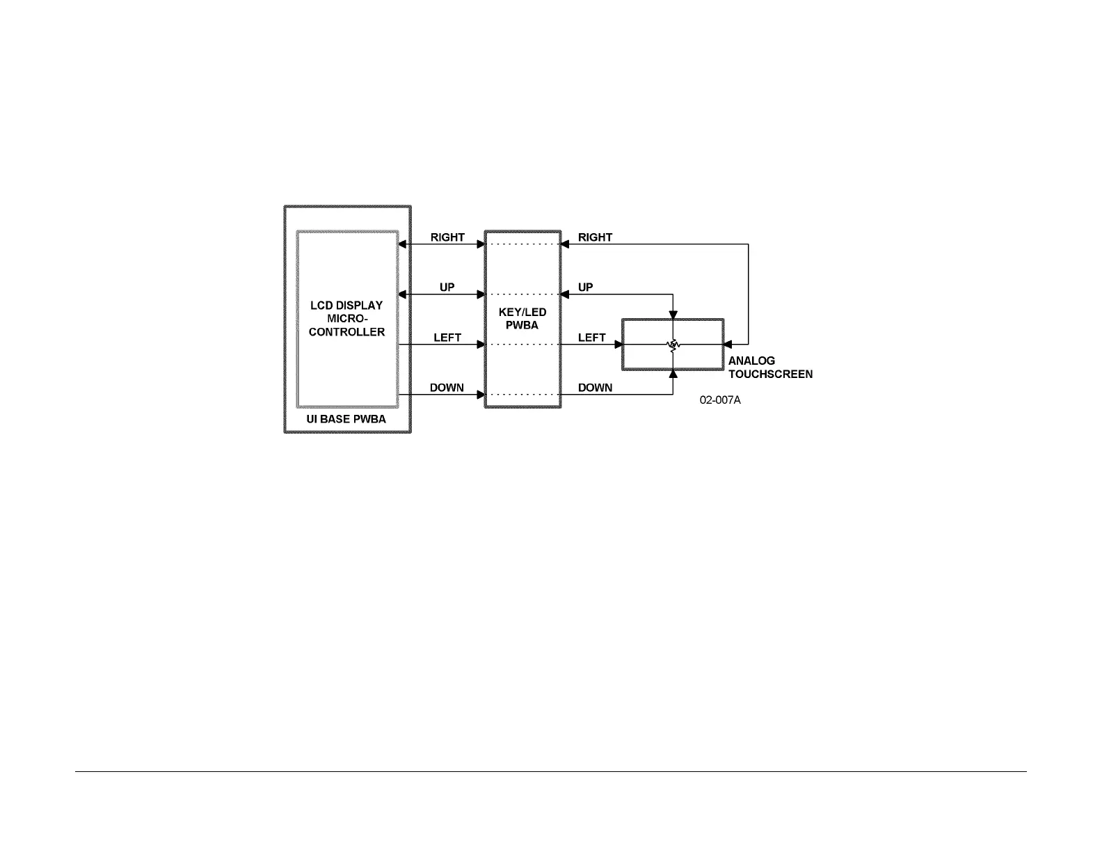
The Analog Touch Panel is mounted over the LCD Display PWBA. As shown in Figure 1, the
touch panel is connected to the UI Base PWBA via the Key/LED PWBA by four analog input/
output lines. The LCD Display Microcontroller on the UI Base PWBA alternately samples the
touchscreen’s X dimension and its Y dimension. These samples alternate rapidly enough that
when the user presses the touchscreen, at least one X dimension measurement and at least
one Y dimension measurement are taken.
The LCD Display Microcontroller takes a Y dimens
ion measuremen
t by driving the Y dimen-
sion lines (Up and Down) as outputs and accepting the Right X dimension line as an input.
When used as a
n output, the Up output is grounded and a Down output is at about +5 VDC.
When the panel is touched, two internal conductive layers make contact. The voltage at the
Right input is proportional to the Y position where the touch occurred.
The X dimension input is taken in a similar fashion.
The LCD
Display Microcontroller drives the
X dimension lines and samples the Up line as an input. When driven, Right is at ground and
Left is at about +5 VDC.
Figure 1 Analog Touchscreen Interconnect Block Diagram

 Loading...


