1/05
9-38
DocuColor 12/DCCS50
Reissue
Installation Instructions
CAUTION
it is possible that there is a shorting condition between the EPC Scan Cable and the FPC-ROS
Flat
Cable connector (P/J 398). Foam on top of the connector is intended to insulate the pins
from contact. However, the foam can be compressed by the EPC Scan Cable and the pins may
stick through and short against the Scan Cable connector housing.
Using a sheet of transparency or shim stock, cut a strip 45mm X 12mm and adhere to the top
of
the foam
on the FPC-ROS Cable connector (P/J 398). This strip will function as an insulator.
NOTE: The 80 to 68 pin EPC Scan Cable is longer in length than the 80 to 80 pin Print Cable.
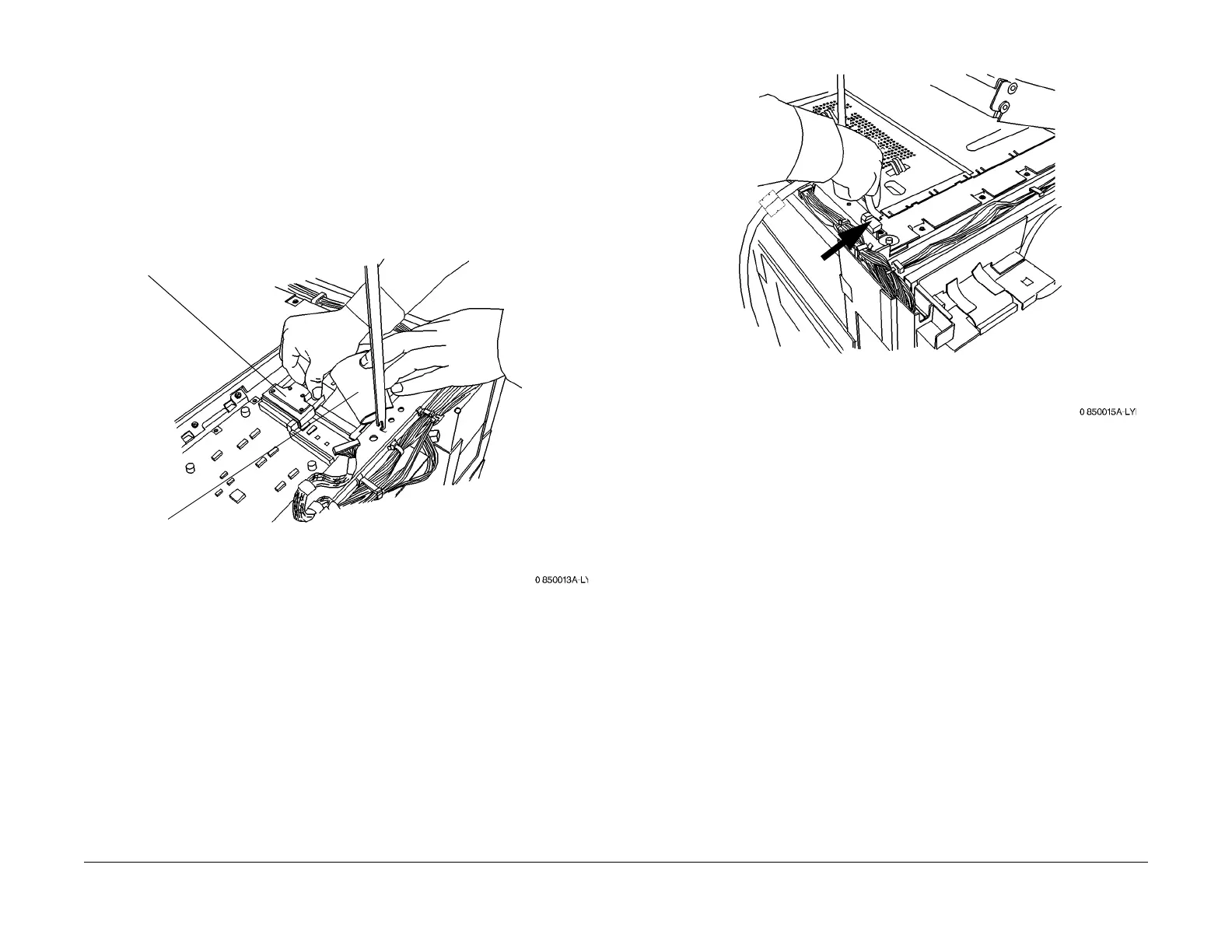
Connect the Scan Cable (Figur
e 2):
Figure 2 Connecting the Scan Cable
13. Reinstall the Half Tone PWB Cover. Route the Scan Cable as shown in Figure 3.
F
igure 3 Routing the Scan Cable
14. NOT
E: Do not reinst
all the Right Upper Cover after closing the IIT. The Right Upper Cover
will be reinstalled, later in these instructions.
Close the IIT (REP 3.1.
2)
15. If the EPC Kit is being installed at the same time as the enablement kit: Perform
Print
Cable Installation step 2 in the EPC Kit installation instructions, then resume this proce-
dure at Step 17.
16. Route the Scan Cable (and Print Cable if present) as shown in F
igure 4
:
2
Connect the Scan Cable to
TSJ1
3
Reconnect the flat cable.
Ensure that the cable is routed
under the frame
1
Disconnect the flat
cable (P/J389)
manuals4you.commanuals4you.com

 Loading...


