1/05
9-39
DocuColor 12/DCCS50
Installation Instructions
Reissue
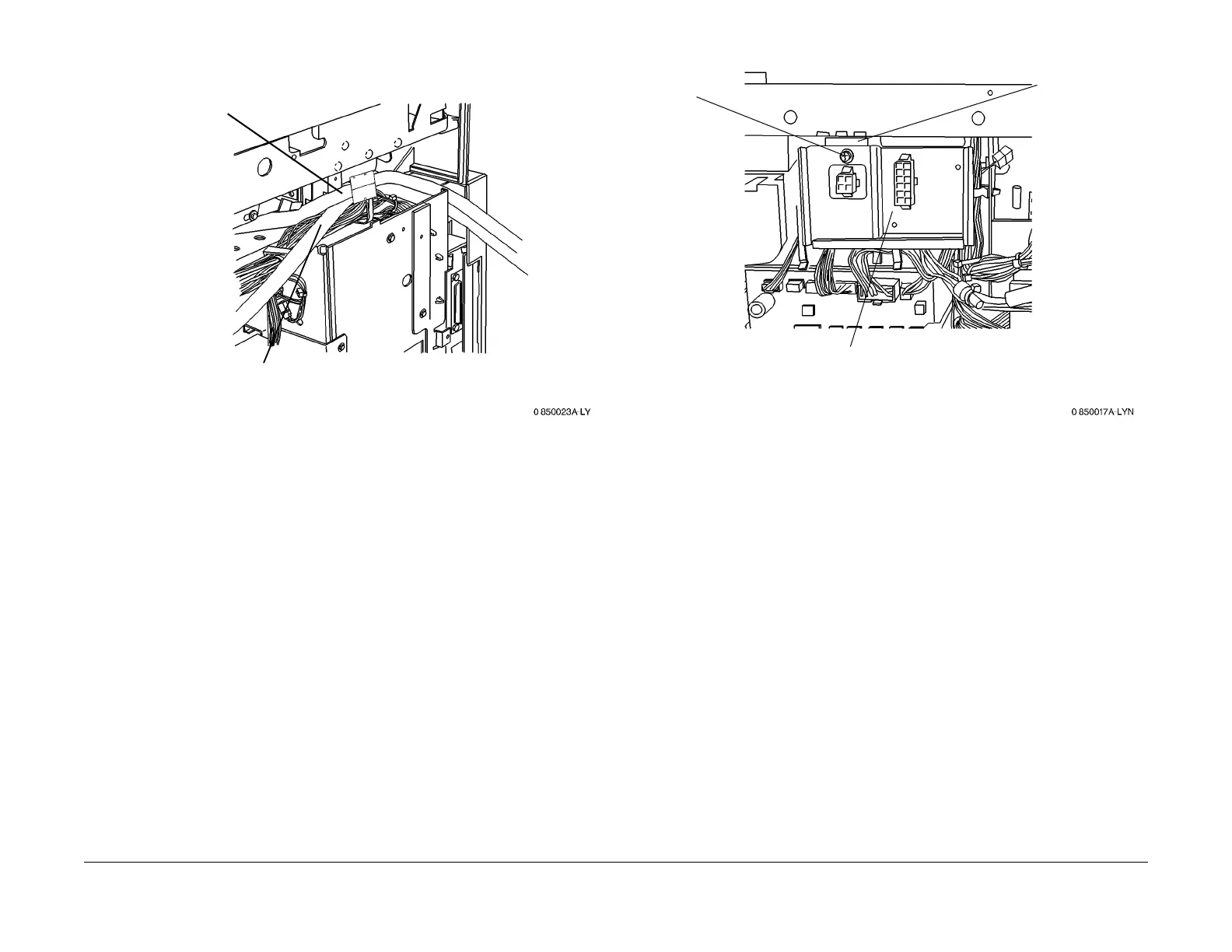
Figure 4 Routing the Scan Cable and Print Cable
17. If the EPC Kit is being installed at the same time as the enablement kit: Pe
rform Print
Cable Installation (steps 4 and 5) of the EPC Kit installation instructions, then resume this
procedure at Step 19.
18. Reinstall the following:
• Exit Tray (PL 12.11)
•
Right Upper Cover (PL 11
.2)
• IIT Rear Cover (PL 1
1.3)
• Wing Tray (PL 11.1)
, If Present
• Convenience Stapler, If present.
Installing the Harness Assembly
1. Remove the Tray Module Rear Cover (PL
11
.3).
2. Remove the existing Connector Bracket (Figu
re 5):
Figure 5 Removing the Connector Bracket
3. Install the EPC Harness Assembly:
a. Disconnect P/J22 fr
om the IOT LVPS.
b. Connect J22A (new harness) to P22 on
the IOT LVPS.
c. Connect J22 (existing harness) to P22A (new harness).
d. Disconnect P/J21 fr
om the IOT LVPS.
e. Connect J21A (new harness) to P21 on
the IOT LVPS.
f. Connect J21 (existing harness) to P21A (new harness).
4. Install the new Connector Bracket (Figu
re 6):
1
Route the Print cable
towards the rear of the
machine
2
Route the Scan cable,
with the ferrite in front of
the Print cable, towards
the rear of the machine
1
Remove the
screw (1)
2
Slide bracket left
then down, to
remove
3
Detach P/J 899

 Loading...


