1/05
6-21
DocuColor 12/DCCS50
General Procedures
Reissue
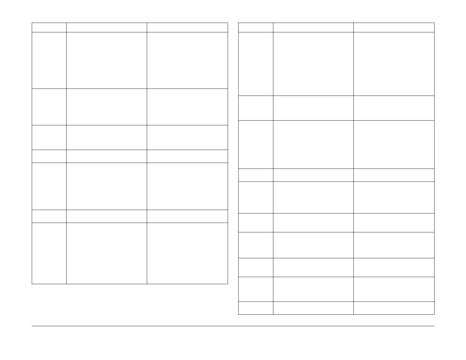
132 Set Machine Serial Number.
Read Billing Meter Information
If you have replaced the PWB that
has a Machine Serial Number, check
the PWB and set the Machine Serial
Number.
Reads Billing Meter Information for
t
he fo
llowing:
•IOT CPU PWB
• Half-Tone PWB
•IOT NVM PWB
135 Service Data
HFSI Counter
Displays the regular part replacement
life
expectancy (threshold) and cur-
rent value (usage). You can change
t
he replacem
ent life expectancy to a
preset value in the PWS database
and reset the current value.
140 Component Check: Analog Monitor Monitor the analog values of the sen-
sors (A/D conversion) while operating
t
he comp
onents (e.g., C.C). You can
temporarily change the output value.
188 Service Mode Exit Screen Displays the requirements for exit
f
ro
m the Service Mode.
301 NVM access: NVM initialization Commands NVM Data initialization
for
initialization of:
•IISS
• Post IPS
•IOT
•SYS
•UI
305 System Test: Component Operation
Check UI
Component Check
Checks the UI Screen and Compo-
nent Panel Button operation.
330 Component Check: Component Con-
trol
Displays the instructions and results
of the
Input Component Check and
Output Component Check
1. You can monitor each Input
Comp
onent or check
the opera-
tion of each Output Component.
2. You can simultaneously check
mult
ip
le Input Components and
Output Components up to 11
total.
Table 1 dC Routines
d
C Nu
mber Name Description
351 NVM Background Processing 1. Saves and restores values of all
NVM in PWS dC131 databank.
NOTE: Background Read must
compl
ete prior to saving.
2. Start and Stop background NVM
Read.
3. Sav
es/restores machine set-
tings. Saves NVM values listed:
4. Resets all HFSI.
361 NVM access: Save/Restore NVM Saves the machine NVM data in the
PWS.
Restores the machine NVM
data (stored in the PWS) back to the
machine.
371 Configuration Page Allows viewing of current software
vers
ion and Mar
ket Place setting,
Machine Configuration, Output
Device(s), Accessories, Tray 1 Paper
Size setting, Feature Config., and
Input Device.
These settings can be changed to
align wit
h the m
achine configuration.
391 Edit Pad Can change the Edit Pad custom
color(s).
612 Color Tes
t Pattern Print 1. Outputs a test pattern to identify
a copy quali
ty problem.
2. Generates a test pattern from
the
Pattern Generator in the
machine.
701 Other Adjust/Set: Fuser Nip Measure-
ment
Make a copy for a contact arc adjust-
ment and measure the fuser nip width
by
a si
mple operation.
740 Tray 5 (Bypass) guide adjustment 1. Re-calibrate Size Sensor
2. Check if the Tray 5 guide size in
the
width direction has been
properly detected.
915 Machine data output: XERO data dis-
play
Displays the machine Xerographic
dat
a in t
he PWS in a format that is
easy to see and understand.
918 IOT Highlight Setup Uniform the Highlight Density Repro-
duction Starting Point (for each K, Y,
M,
C)
and the Highlight Density of In/
Out.
919 Color Balance Setup
(IIT machine only)
Make a 4C copy in the Photo mode.
Adjus
t t
he YMCK color balance.
Table 1 dC Routines
d
C Numb
er Name Description

 Loading...


