1/05
10-24
DocuColor 12/DCCS50
Electrical Interlocks
Reissue
Principles of Operation
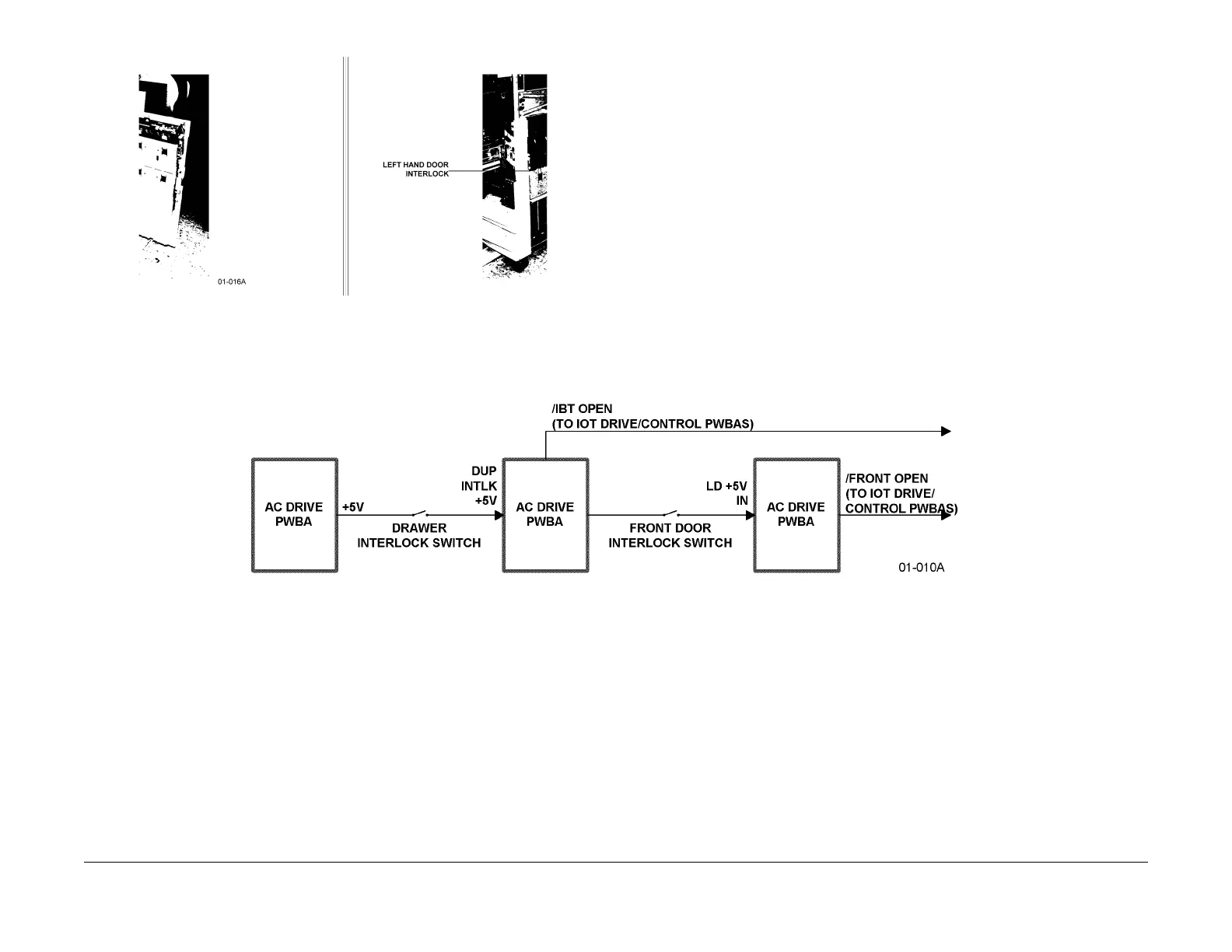
Figure 2 Inverter Cover (L/H Door) Interlock Switch Location
Whenever an interlocked assembly is opened, the as
sociated interlock switch disconnects
power from the supplied circuitry.
• +5 VDC is interlocked by the machine paper path Drawer and front door. F
igur
e 3 shows
the associated signal routing.
• +5 VDC is interlocked by the machine Inverter Cover
• +24 VDC is interlocked by the machine front door Figur
e 4 shows the associated signal
routing.
• +24 VDC is also interlocked by the machine left hand door. Figure 5 sh
ows the associated
signal routing.
Figure 3 Front Door +5 VDC Power Interlock Signal Flow
manuals4you.commanuals4you.com

 Loading...


