1/05
10-89
DocuColor 12/DCCS50
Photoreceptor Exposure
Principles of Operation
Reissue
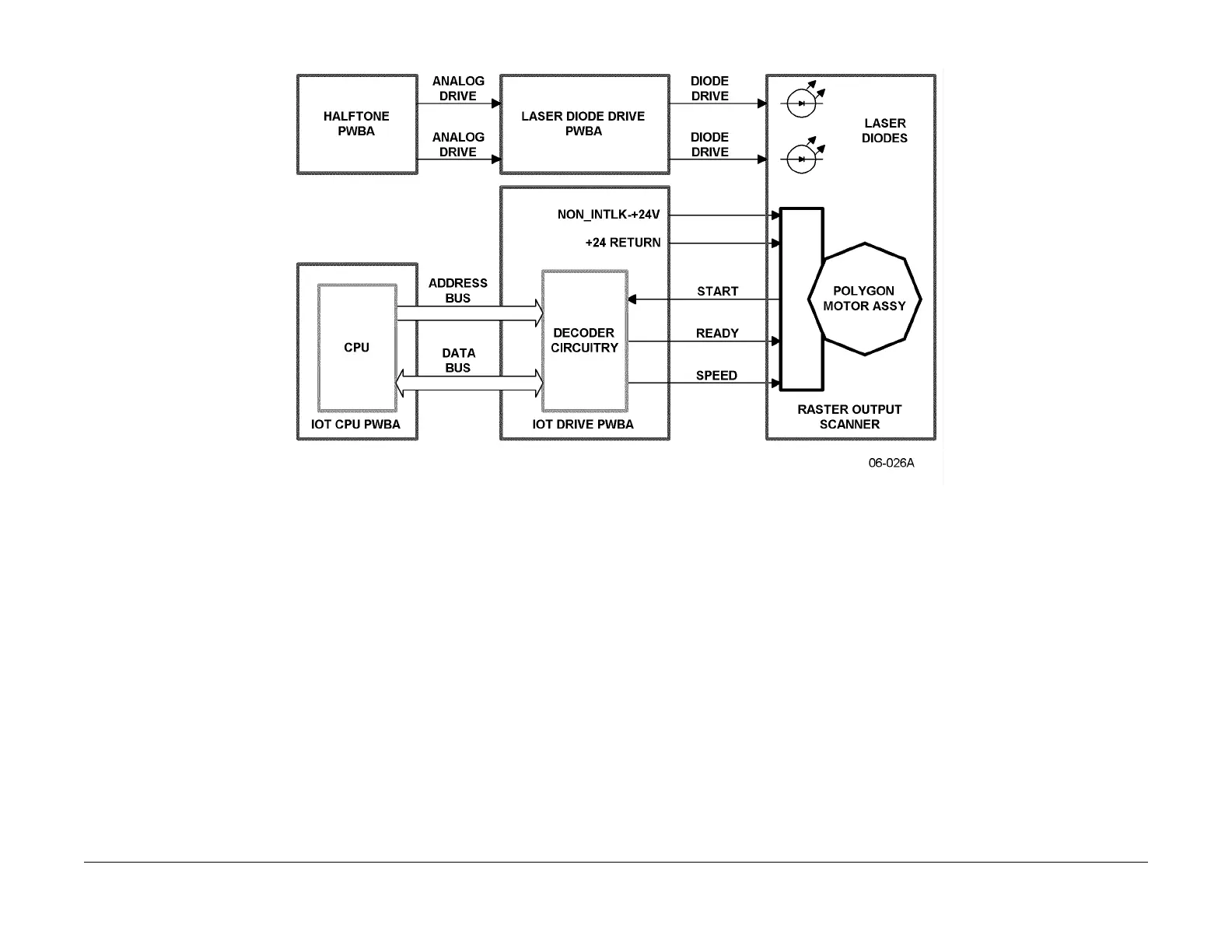
Figure 1 LDD PWBA and ROS Simplified Schematic Diagram
LDD PWBA
The LDD PWBA provides the interface between the Halftone PWBA and the ROS. The LDD
PWBA switches on the ROS laser diodes while the pulse from the Halftone PWBA is active.
See Figure 1.
ROS
The ROS, shown in Figure 2, includes two solid-state diode lasers whose output is directed as
follows:
1. Slit
2. Expander Lens
3. Two Mirrors
4. Rotating 12-sided Polygonal Mirror
5. Scan Ray Mirror
6. Mirror Cylinder
7. Photoreceptor Drum
The output wavelength is 780 nm which is in t
he infr
ared range of the electromagnetic spec-
trum. Therefore, the laser diode outputs are invisib
le to the human eye. By precisely timing
when the LED is lit, the LED output can be reflected from a mirror face anywhere along a line
extending across the width of the photoreceptor drum. The light striking the photoreceptor
drum causes a latent image on the drum.
Since the rotational velocity of the mirror must be both very accurate and stable, the mirror is
moun
ted on
air bearing. Control signals for the ROS are provided by the IOT Drive PWBA,
under the control of the IOT CPU. The IOT LVPS provides +24 VDC via the IOT Drive PWBA.

 Loading...


