1/05
4-95
DocuColor 12/DCCS50
REP 6.7.1
Repairs and Adjustments
Reissue
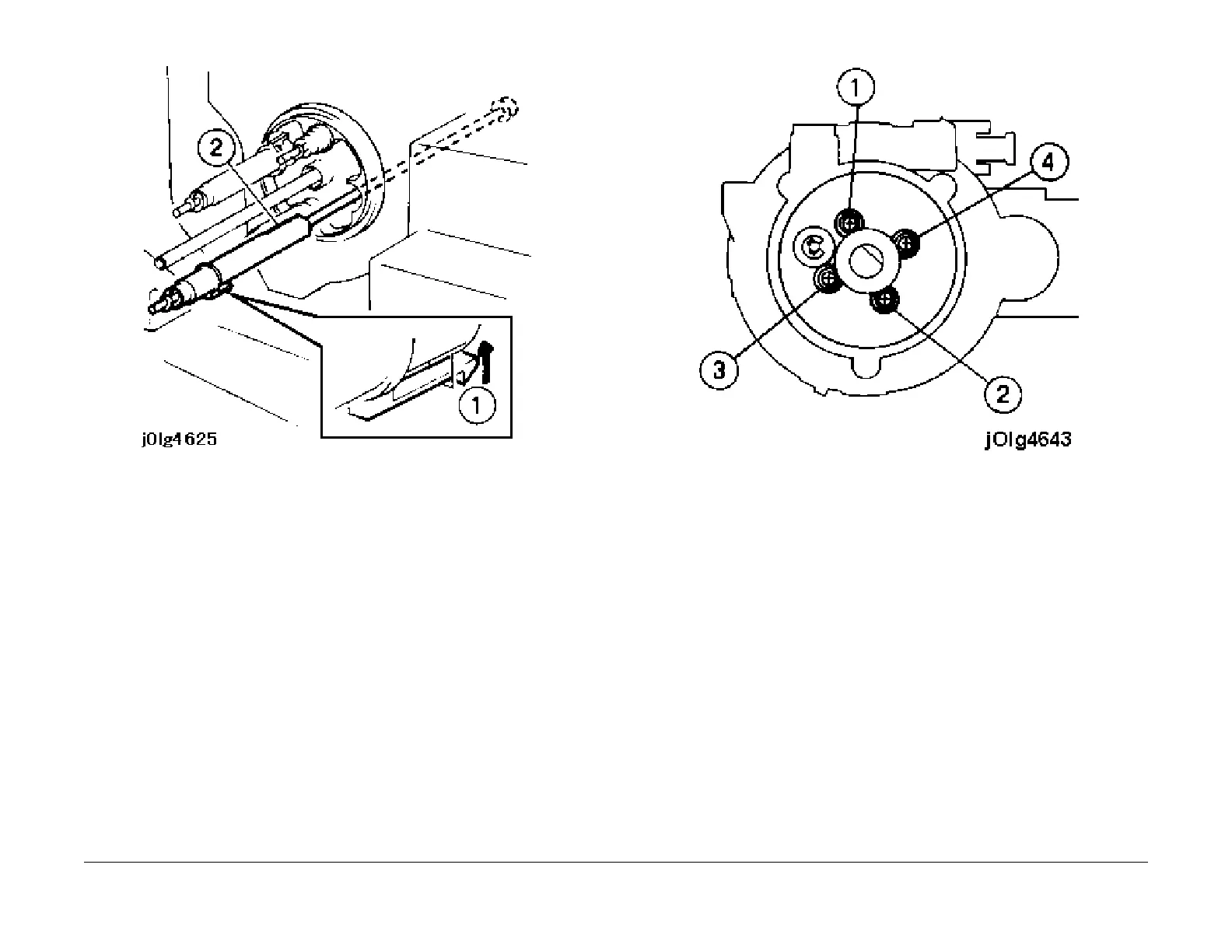
Figure 6 Remove the Rotary Auger
Installation
a. Reinstall the parts in the reverse order of disassembly until the installation of the Four (4)
screws that secures the Inner Dispense Cover.
NOTE: The following procedure is instructions for tightening the four (4) screws that
secure th
e Inner Dispense Assembly.
b. This procedure is to EVENLY distribute the torque throughout the Rotary Dispenser.
c. Do not use Power Screwdrivers.
d. Install the screws (3) that secure the Outer Dispense Assembly (PL 6.5) (only the sc
rews,
not the Outer Dispense Cover). This will secure the Dispense Assembly and align the
Inner Dispense Assembly.
e. Hand tighten the screws (4) until the lock washer closes (locks) in the sequence shown
(Fi
gu
re 7).
f. DO NOT OVER TIGHTEN
Figur
e 7 Tightening Sequence
g. Because of the “Counter Reaction” torque from each screw,
retighten the screw in the
same sequence by turning each screw 1/4 (one quarter) of a turn (90 degrees).
h. Repeat step g.
i. Remove the screws (3) that were installed in step d.
j. Continue the reassembly process.

 Loading...


