CHYRON Corporation
Installation 2-14 Revision D
5HDU9LHZ0$;!
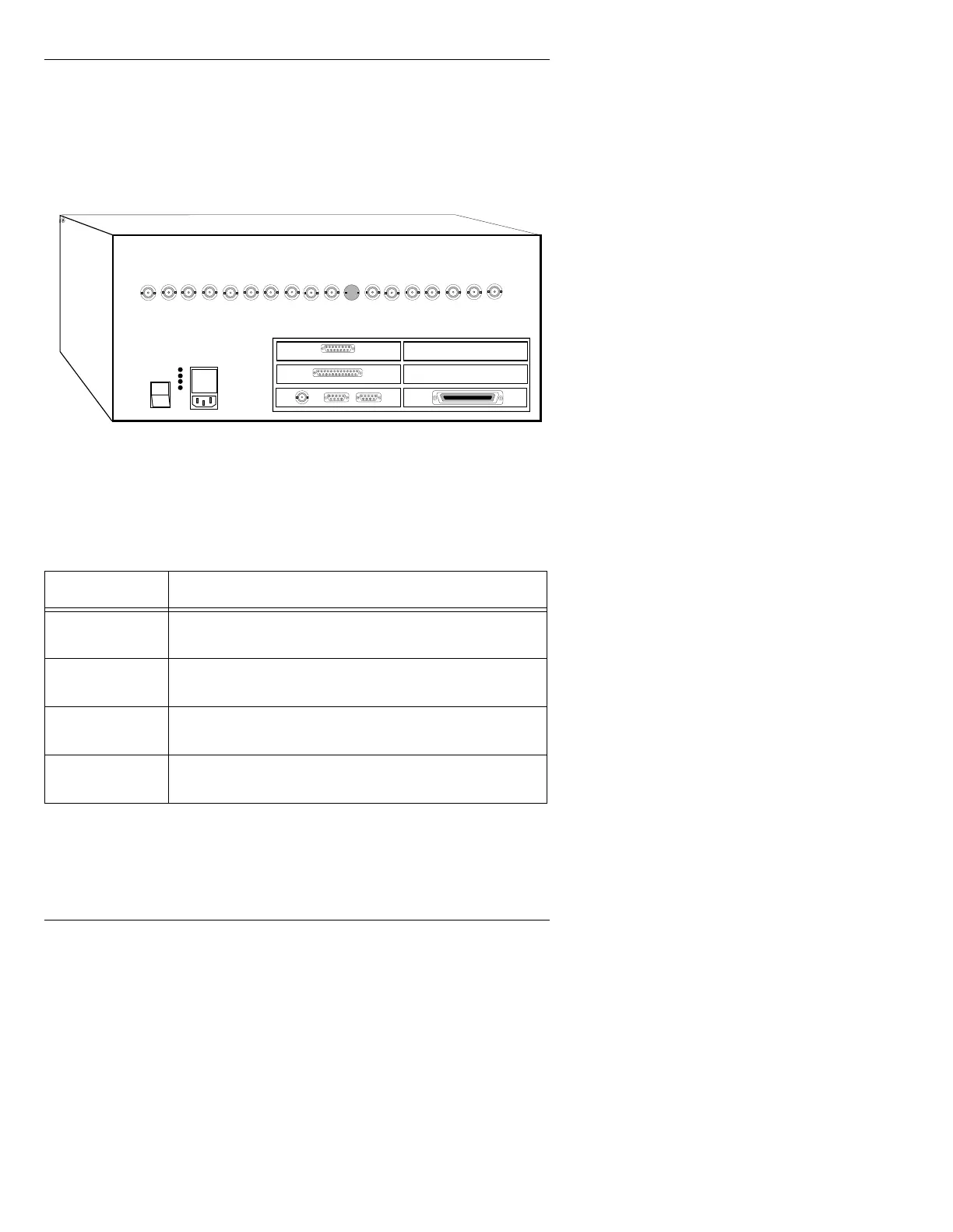
Input and output connections to MAX!> are made through con-
nectors on the rear panel of the main chassis (Figure 2-9):
Figure 2-9. MAX!> Rear Panel Connections
Table 2-3: MAX!> Rear Panel Connections
&RQQHFWRU 'HVFULSWLRQ
AC IN
Connect the supplied power cord to the rear panel recep-
tacle, and to a grounded outlet in your facility.
Test Points
Three chassis power supply test points (+5v, -12v, +12v)
are provided, along with a ground reference.
ArcNet
Run ArcNet coaxial cable from this connector to the J2
BNC on the MAX!> keyboard.
Serial Ports
The two D9 serial ports on the rear panel are used for
options such as Logo Compose, etc.
1
0
CHANNEL 1
CHANNEL 2
Keyboard/Serial Ports Interface Panel
CHYRON VIDEO
COLOR EDIT
SYNC
BLUE
GREEN
RED
KEY
PROMPT
GENLOCK
SYNC OUT
PROMPT
KEY
RED
GREEN
BLUE
SYNC
COLOR EDIT
CHYRON VIDEO
ETHERNET
GPI
SCSI PORT
(Option)
(Option)
(Option)