iNFiNiT! Family Operation Manual
Revision D 2-23 Installation
0$;,1(*3,+RRNXS
The GPI connector on the MAXINE! rear panel can be used to
activate Function Keys
F1
through
F8
.
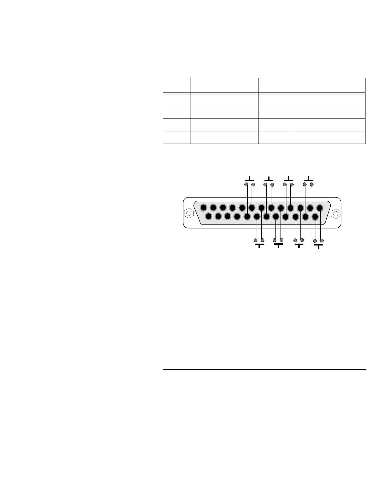
Figure 2-14 shows the pinout of the DB-25 (female) GPI con-
nector, with the corresponding Function Keys:
Figure 2-14. MAXINE! GPI Connector Pinout
$QDORJ9LGHR$GMXVWPHQWV
4XDOLILHG7HFKQLFLDQV21/<
NOTE
iNFiNiT! Family systems are properly
aligned before shipment. Video
adjustments are necessary only if, after
connecting monitors, you have problems
with color or picture stability.
Table 2-9: MAXINE! GPI Connector Pinout
).H\ & RQQHFWRU3LQV ).H\ &RQQHFWRU3LQV
F1
Pins 1 and 14
F5
Pins 5 and 18.
F2
Pins 2 and 15
F6
Pins 6 and 19.
F3
Pins 3 and 16
F7
Pins 7 and 20.
F4
Pins 4 and 17.
F8
Pins 8 and 21.
1
13
14
25
F 1
F 3
F 5
F 7
F 2
F 4
F 6
F 8
MAXINE! GPI Connector Pinout
rear view of connector shown