CHYRON Corporation
Installation 2-16 Revision D
0$;,1(+DUGZDUH 'HVFULSWLRQ
)URQW9LHZ0$;,1(
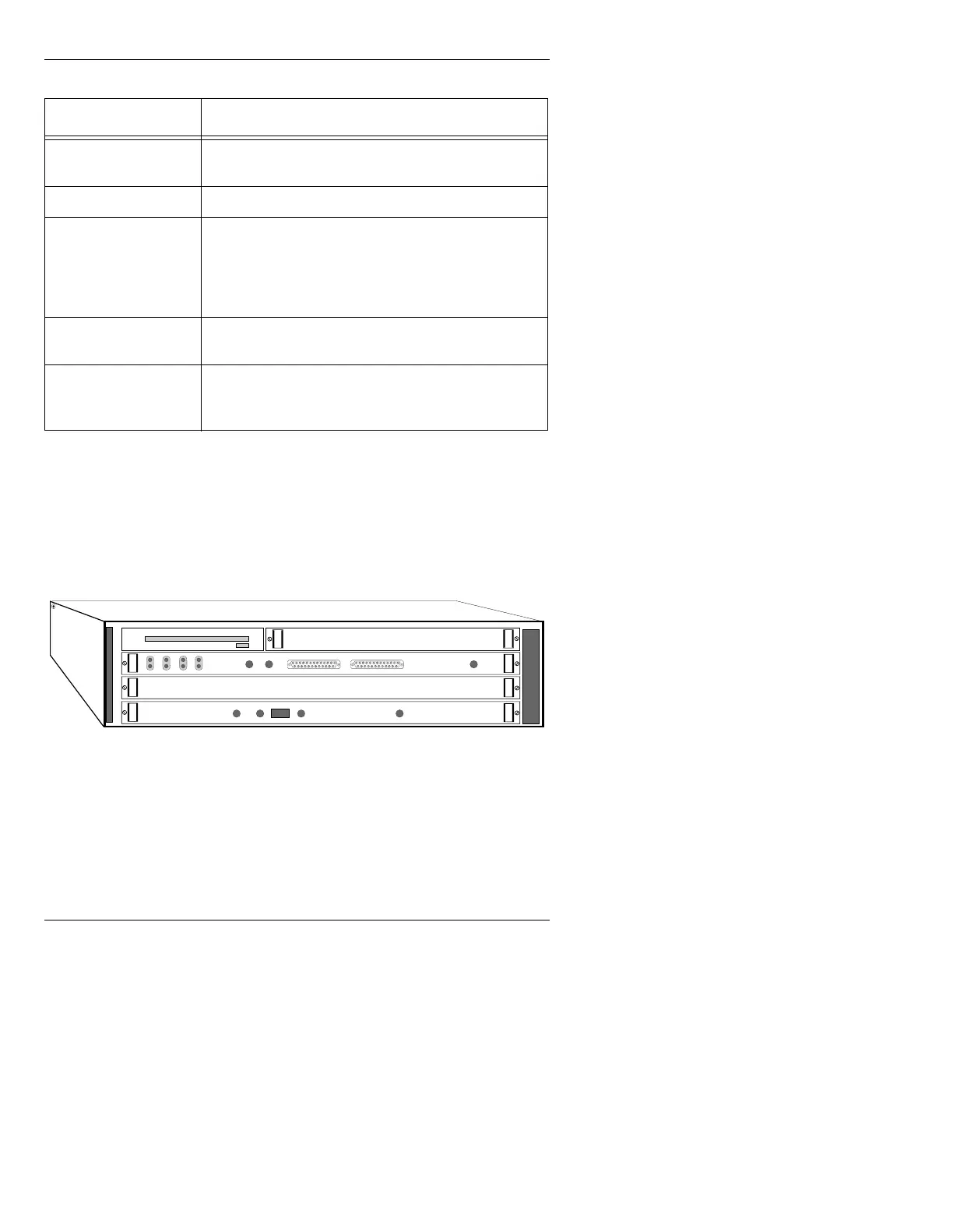
Figure 2-10 shows the MAXINE! mainframe with the front
door open.
Figure 2-10. MAXINE! Chassis Front View
5HDU9LHZ0$;,1(
Input and output connections to MAXINE! are made through
connectors on the rear panel (Figure 2-11).
RED
If RGB/YUV equipped, supplies the red or V com-
ponent from the RGB/YUV board. (0.7v p-p)
KEY
Provides an analog (linear) key output. (1.0v p-p)
PROMPT
Displays icon-based prompts, menus, commands
and current operating information such as mode,
color and font specifications. Connect this output to
a monochrome monitor. Only one Prompt output is
available on MAX!>. (Monochrome)
GEN LOCK
External (house) genlock source input, if MAX!>
internal genlock is not to be used.
SYNC OUT
SYNC OUT supplies the internal MAX!> composite
sync signal to any external equipment.
(4.0v p-p NTSC; 2.0 v p-p PAL)
Table 2-4: MAX!> Video Connections
&RQQHFWRU 'HVFULSWLRQ
CPU BOARD
FLOPPY DISK DRIVE
Video Input Module (Option)
AIR FILTER
ABORT
RESET
FAIL STAT
RUN SCON
LAN FUSE
SCSI VME
FRAME BUFFER
Video or 601