CHYRON Corporation
Installation 2-6 Revision D
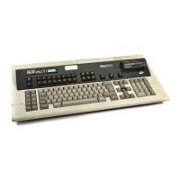
.H\ERDUG,QVWDOODWLRQ0$;,1(
NOTE
A 25-foot keyboard cable is supplied for
connecting the keyboard to the system
chassis.
• Place the keyboard on a level, secure surface, and allow
access for the keyboard and AC power cables.
• Turn the keyboard power switch OFF, then connect the
supplied AC power cord between the keyboard and a prop-
erly grounded power outlet.
• Connect one end of the supplied keyboard cable to the
KEYBOARD
connector on the MAXINE! rear panel, as
shown in Figure 2-3.
•
Mouse (optional):
Connect the serial Mouse to the
Mouse port on the MAXINE! rear panel, as shown in Fig-
ure 2-3.
• Connect the other end of the keyboard cable to the
KEY-
BOARD OUT
connector on the keyboard’s rear panel, as
shown in Figure 2-4.
•
Multiple Keyboards:
To use multiple keyboards on a
MAXINE! system, simply daisy-chain the keyboards from
the
KEYBOARD IN
to
KEYBOARD OUT
connectors.
No termination is required for MAXINE! keyboards.
Mouse Option
If you have the mouse option, connect the
mouse cable to serial port J1, and then con-
firm the DIP switch (#10) on the keyboard
underside is set correctly (see §2.10).
Keyboard Priority
(iNFINiT! Only)
Priority can be changed so that KBD 2 has
priority over KBD 1, but only KBD 1 can
issue the change of priority. See Section 3 for
more information on system setup.