CHYRON Corporation
Installation 2-22 Revision D
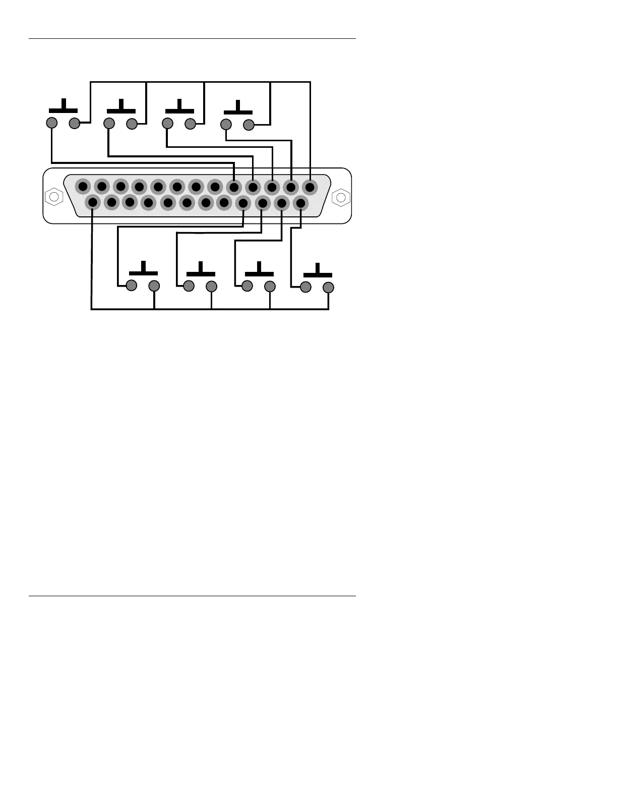
Figure 2-13 shows the pinout of the DB-25 (male) GPI connec-
tor, with the corresponding Function Keys:
Figure 2-13. MAX!> GPI Connector Pinout
NOTE
When wiring the GPI inputs, remember
that Pin 1 is the “common” for GPI
contact closures F2, F4, F6, and F8, while
Pin 25 is the “common” for GPI contact
closures F1, F3, F5, and F7.
1
13
14
25
F 1
F 3
F 5
F 7
F 2
F 4
F 6
F 8
Rear view of connector shown