iNFiNiT! Family Operation Manual
Revision D 2-33 Installation
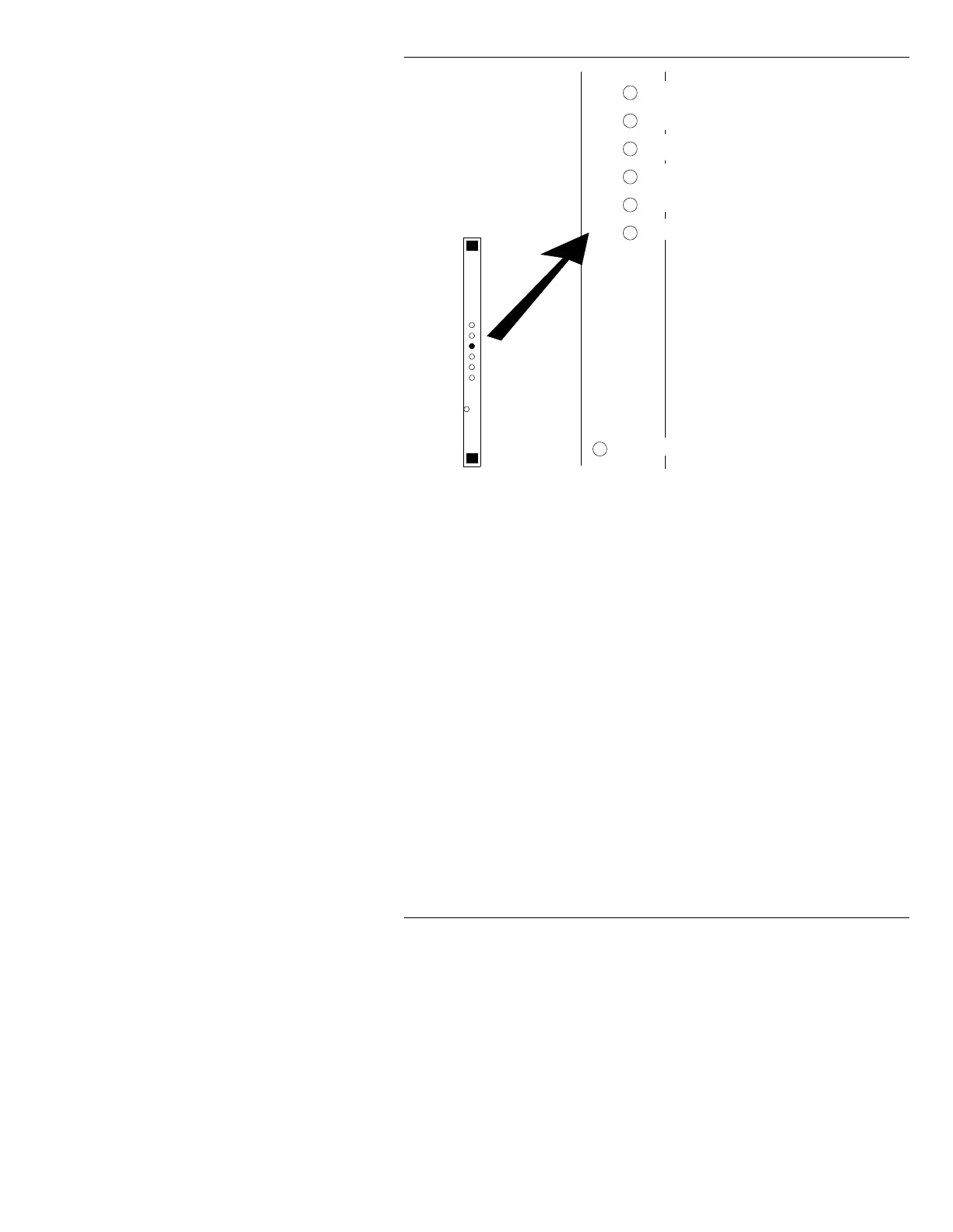
Figure 2-16. iNFiNiT! 601 Board Adjustments
SW1
Luminance Timing. Adjusts the position of the luminance signal
with respect to the chrominance. This adjustment moves the posi-
tion of the video data along the scanline.
SW2
Chrominance Timing. Adjusts the position of the chrominance sig-
nal with respect to the luminance signal. This adjustment also
moves the position of the video data along the scanline.
SW3
Hot Key Enable/Disable; as switch is rotated, click to enable/dis-
able Hot Key (~30mV increase in key level).
SW4
Output Bit Clock Phase. Adjusting this switch moves the 601 “27
MHz” output clock with respect to output data, in 3ns increments.
SW5
Input Bit Clock Phase. This switch is for factory use.
SW6
Key Timing. This switch is used to position the output key signal
with respect to the output video.
LED
LED indicates that incoming video data is NOT present, or is NOT
valid. Check condition of incoming video if LED is on.
SW4 - Output Bit Clock Phase
SW5 - Input Bit Clock Phase
SW1 - Luma Timing
SW2 - Chroma Timing
SW6 - Key Timing
LED - ON = no incoming video
601
Board
SW3 - Hot Key