CHYRON Corporation
Installation 2-20 Revision D
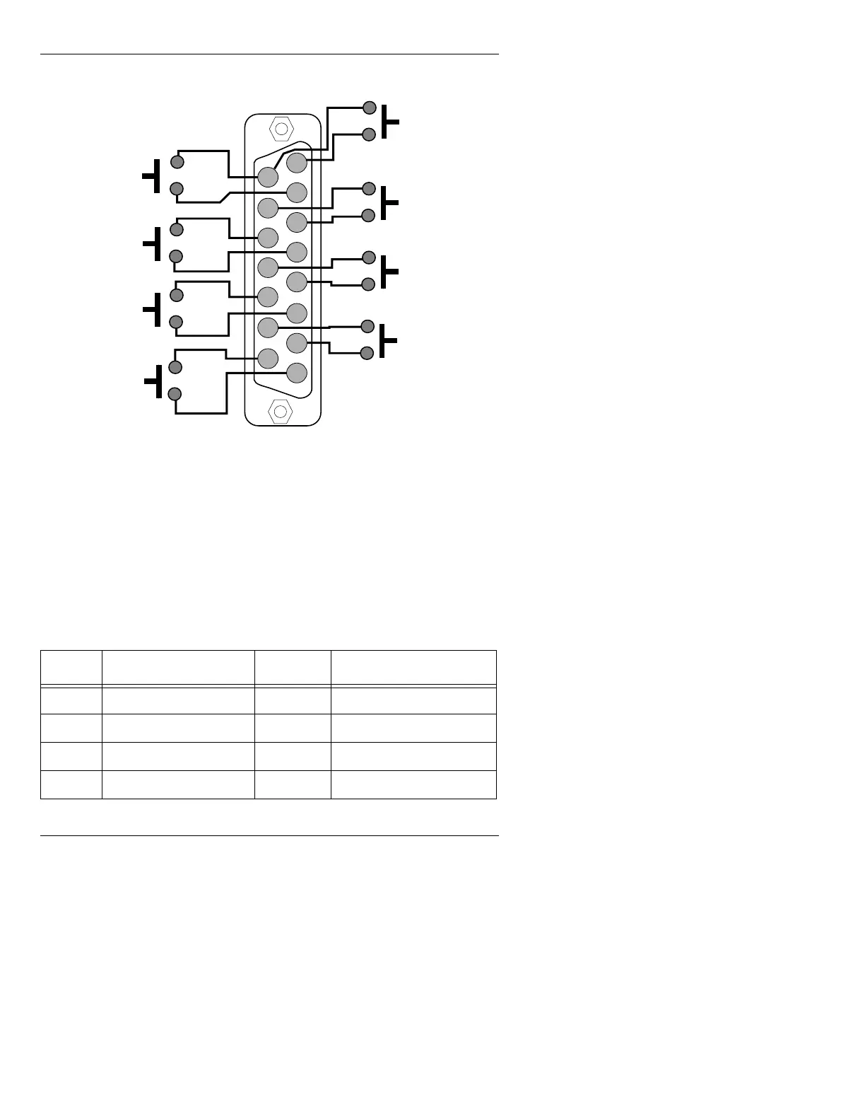
Figure 2-12 shows the GPI connector pinout:
Figure 2-12. iNFiNiT! GPI Connector Pinout
The normally open single-pole switches are shown only for
illustration, and are not included with the system. Any type of
momentary switching device can be used, but switch contact
bounce time must be 20 ms or less.
Connector pins correspond to Function Keys as follows:
Table 2-7: iNFiNiT! GPI Connector Pinout
).H\ & RQQHFWRU3L QV ).H\ &RQQHFWRU3LQV
F1
Pins 8 and 15
F5
Pins 4 and 12.
F2
Pins 7 and 15
F6
Pins 3 and 11.
F3
Pins 6 and 14
F7
Pins 2 and 10.
F4
Pins 5 and 13.
F8
Pins 1 and 9.
18
15 9
F3
F1
F5
F7
F4
F2
F6
F8
Rear view of Male DB-15 connector
pins 9 throu
h 15 are GNDs