Requirements
This example uses the following hardware components:
•
Four MX Series 3D Universal Edge Routers for Router PE1, Router PE2, Router PE3, and
Router PE4
•
One M Series Multiservice Edge Router for Router CE4
•
Two EX Series Ethernet Switches for Device CE1 and Device CE2
•
One J Series Services Router for Router CE3
Overview and Topology
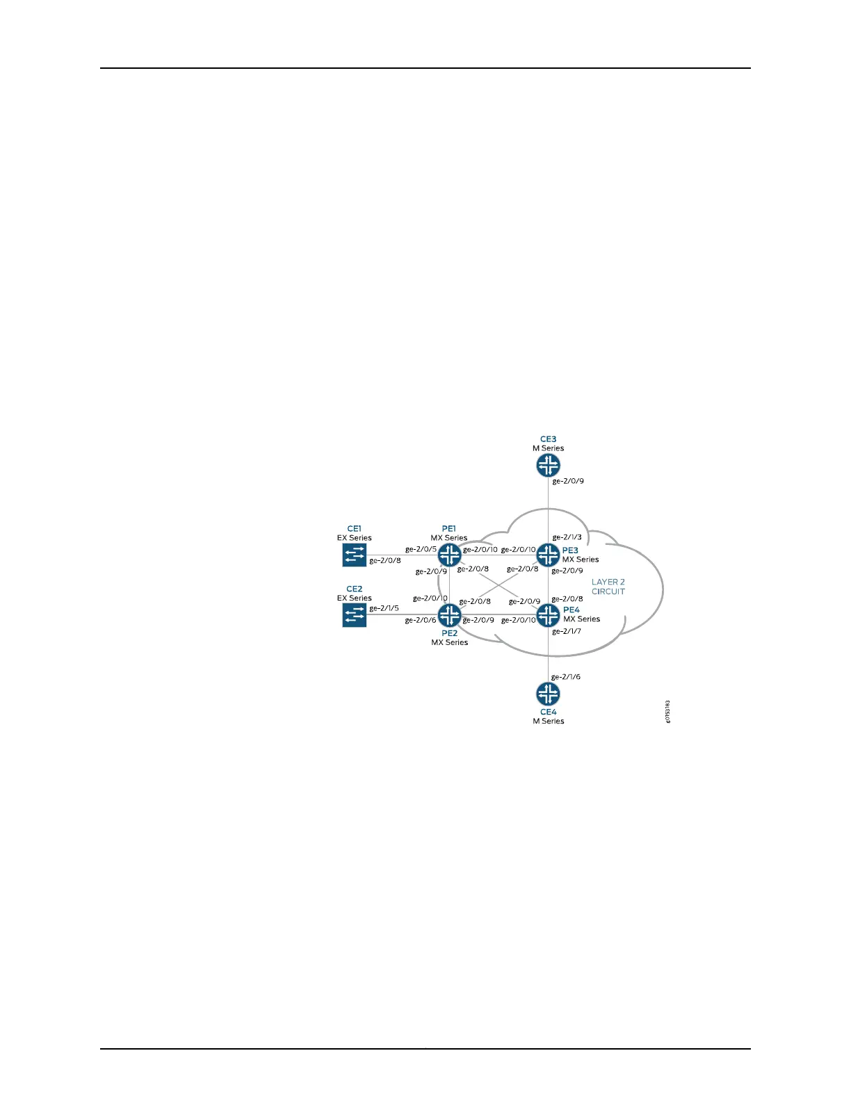
Figure 65 on page 1283 shows the physical topology used in this example.
Figure 65: Physical Topology of H-VPLS
The following describes the base configuration used in this example:
•
Router PE1 and Router PE2 are configured as MTU devices.
•
Router PE3 and Router PE4 are configured as PE-r routers, each using an LDP-based
VPLS routing instance.
•
The LDP and OSPF protocols are configured on all of the MTU devices and PE-r routers.
•
Core-facing interfaces are enabled with the MPLS address family.
•
Optionally, the VPLS routing instances can be configured on PE-r routers with the
no-tunnel-interface statement. This allows the routers to use a label-switched interface
(LSI), which is useful if your routers do not have Tunnel Services PICs or built-in support
for tunnel services.
1283Copyright © 2017, Juniper Networks, Inc.
Chapter 35: Configuring Virtual Private LAN Service