Table 26 on page 158 describes the fields used for hashing by Layer 3 services. The table
explains the default behavior and the configurable fields based on the type of traffic
received on the Layer 3 service
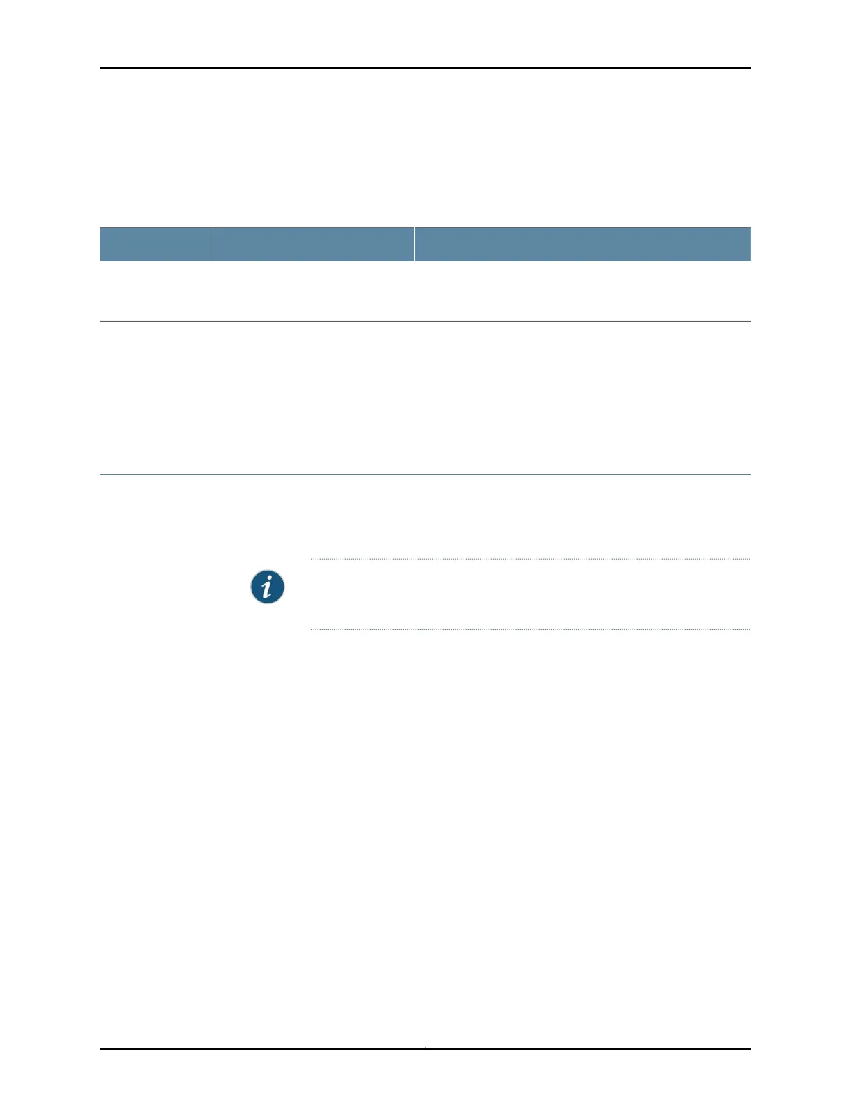
Table 26: Hashing Behavior for IP Services
Configurable Fields (Hash keys)Default Hash FieldsTraffic Type
Layer 3 (Source IP and/or| destination IP)
Layer 4 (UDP/TCP source port andr UDP/TCP destination port)
Source IP and Destination IPIP
Related
Documentation
CoS on ACX Series Universal Access Routers Features Overview on page 864•
• Controlling Network Access Using Traffic Policing Overview on page 908
• Standard Firewall Filter Match Conditions and Actions on ACX Series Routers Overview
on page 1052
User-Defined Alarm Relay Overview
The ACX Series router alarm contact port—labeled ALARM on the front panel—allows
you to manage sensors and external devices connected to the router in remote unstaffed
facilities.
NOTE: Alarm contact port is not applicable on ACX5048 and ACX5096
routers.
•
Alarm Contact Port on page 158
•
Alarm Input on page 158
•
Alarm Output on page 159
Alarm Contact Port
The ACX Series router alarm contact port is a 15-pin D-type dry contact connector for
alarms. The alarm contact port is used to generate LED alarms on the router and to turn
external devices on or off. You can connect up to four input alarms and two output alarms.
The alarm setting is open or closed.
Alarm Input
Alarm input provides dry contacts to connect to security sensors such as door or window
monitors. The alarm input—open or closed—is sensed and reported to the management
software. You can configure up to four alarm input relay ports (0 through 3) to operate
as normally open or normally closed, and to trigger a red alarm condition or a yellow
alarm condition or to ignore alarm conditions.
Copyright © 2017, Juniper Networks, Inc.158
ACX Series Universal Access Router Configuration Guide