•
All of the routers are configured with loopback IP addresses.
•
BGP is configured on the PE-r routers. Optionally, you can configure route reflection.
This is useful for scaling internal BGP (IBGP). The BGP configuration includes the
signaling statement at the [editprotocolsbgp group group-name familyl2vpn] hierarchy
level to support Layer 2 VPN signaling using BGP.
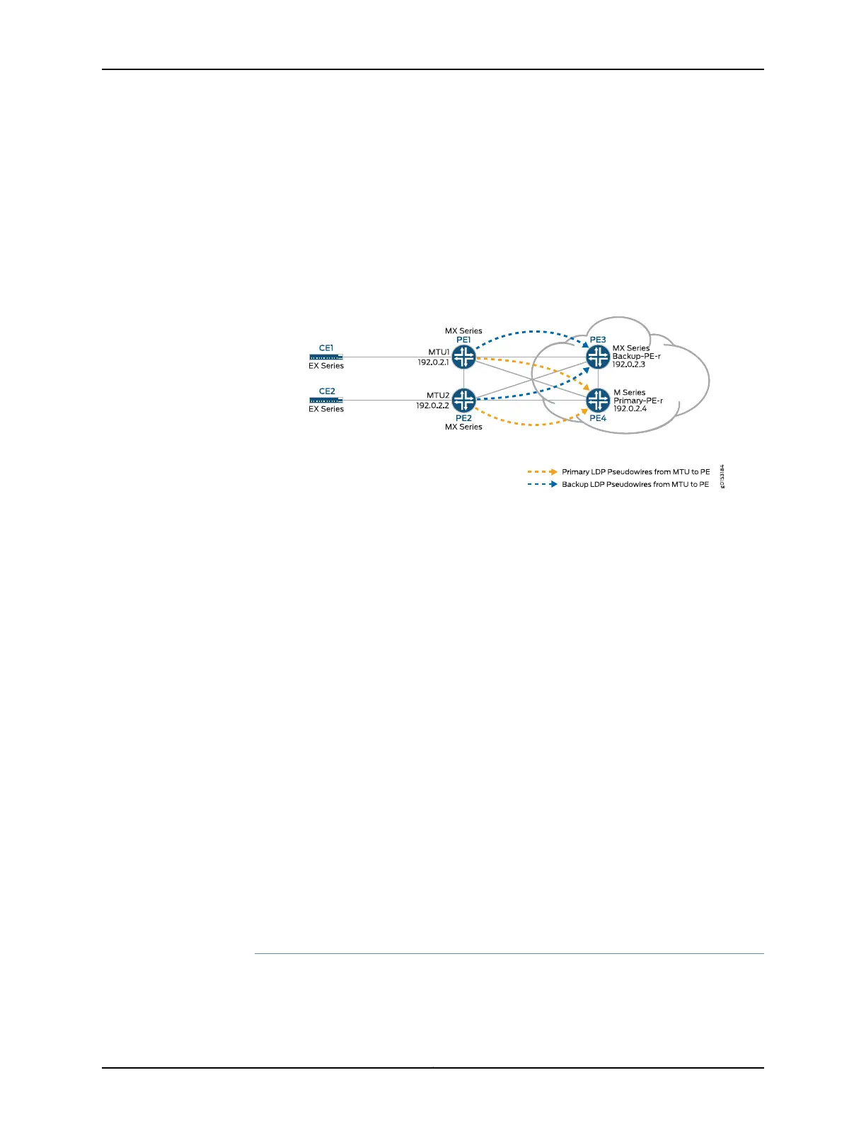
Figure 66 on page 1284 shows the logical topology used in this example.
Figure 66: Logical Topology of H-VPLS
In Figure 66 on page 1284:
•
The MTU devices (Router PE1 and Router PE2) have Layer 2 circuit connections to the
PE-r routers (Router PE3 and Router PE4). For redundancy, a backup neighbor is
configured for the Layer 2 circuit connections to the PE-r routers.
•
The l2circuit statement in the [edit protocols] hierarchy is included on the MTU devices.
•
A VPLS routing instance is configured on the PE-r routers.
•
In the VPLS routing instance on the PE-r routers, mesh groups are created to terminate
the Layer 2 circuit pseudowires that originate at the MTU devices.
•
Each MTU device is configured with a different virtual circuit ID.
•
Each PE-r router’s mesh groups configuration includes VPLS ID values that match the
virtual circuit IDs used on the MTU devices.
Configuration
To configure H-VPLS with different mesh groups for each spoke PE-r router using
BGP-based VPLS, perform the following tasks:
•
Configuring the Spoke MTU PE Routers on page 1284
•
Configuring the Hub PE (PE-r) on page 1286
•
Verifying the H-VPLS Operation on page 1289
Configuring the Spoke MTU PE Routers
Step-by-Step
Procedure
On Router PE1, configure the Gigabit Ethernet interface connected to Router CE1.
Include the encapsulation statement and specify the ethernet-ccc option. Also
1.
Copyright © 2017, Juniper Networks, Inc.1284
ACX Series Universal Access Router Configuration Guide