Overview
H-VPLS uses LDP-based VPLS to signal and establish pseudowires. LDP-based VPLS
is defined in RFC 4762, Virtual Private LAN Service (VPLS) Using Label Distribution Protocol
(LDP) Signaling. RFC 4762 also defines a hierarchical mode of operation for LDP VPLS
called H-VPLS.
VPLS and H-VPLS are different with respect to scaling. VPLS requires a full mesh of
tunnel label-switched paths (LSPs) among all of the provider edge (PE) routers that
participate in the VPLS service. For each VPLS service, n*(n-1)/2 pseudowires must be
set up between the PE routers. In contrast, H-VPLS partitions the network into several
edge domains that are interconnected using an MPLS core. Each edge device only needs
to learn of one local PE device and therefore needs less routing table support. This has
the potential to allow service providers to use relatively less costly devices (such as EX
Series switches) at the customer edge.
NOTE: As alternatives to H-VPLS, Juniper Networks offers other ways to
address VPLS scalability. For more information, see Application Note:
Demystifying H-VPLS.
H-VPLS defines two roles or functionalities:
•
PE-r—PE device that runs VPLS with other PE-r devices, but which also has pseudowires
(it can be based on QinQ access) with another device called a multi-tenant unit (MTU),
which provides the access layer.
•
MTU—PE device that represents the access layer on the H-VPLS architecture and
establishes pseudowires to one or more PE-r devices through which VPLS traffic is
forwarded.
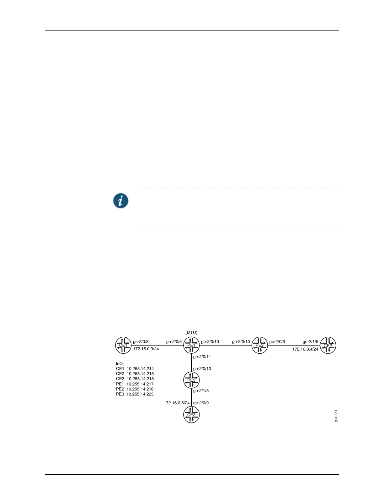
Figure 68 on page 1311 shows the topology used in this example.
Figure 68: Basic H-VPLS With One MTU and Two PE-r Devices
CE1
ge-2/0/8
PE1
ge-2/0/5
172.16.0.3/24
(MTU)
ge-2/0/10
ge-2/0/11
PE2
ge-2/0/10
ge-2/0/6
CE2
ge-2/1/5
172.16.0.4/24
PE3
ge-2/0/10
ge-2/1/3
CE3
ge-2/0/9
172.16.0.5/24
loO:
CE1 10.255.14.214
CE2 10.255.14.215
CE3 10.255.14.218
PE1 10.255.14.217
PE2 10.255.14.216
PE3 10.255.14.225
g041351
The example shows one MTU (Device PE1) connected to two PE-r devices (Device PE2
and Device PE3).
1311Copyright © 2017, Juniper Networks, Inc.
Chapter 35: Configuring Virtual Private LAN Service