Topology
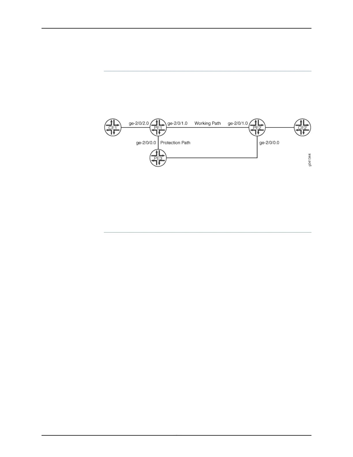
In Figure 43 on page 784, there are two paths running between Router PE1 and Router PE2.
One is the working path between Router PE1 and Router PE2. The other is the protection
path between Router PE1 and Router PE3 to Router PE2.
Figure 43: Connection Protection Using a Pseudowire Configured through
Router PE3 as the Protection Path
Configuration
The following section describes how to configure Layer 2 circuit connection protection:
•
Configuring Connection Protection Using Another PE Router for the Protection
Path on page 784
Configuring Connection Protection Using Another PE Router for the Protection
Path
Step-by-Step
Procedure
To configure Layer 2 Circuit switching protection as shown in Figure 43 on page 784 on
Router PE1:
1. Configure the Layer 2 circuit on Router PE1.
[edit protocols l2circuit]
user@PE1# set local-switching interface ge-2/0/2.0 connection-protection
user@PE1# set local-switching interface ge-2/0/2.0 backup-neighbor 192.0.2.2
virtual-circuit-id 2
user@PE1# set local-switching interface ge-2/0/2.0 backup-neighbor 192.0.2.2
community example
user@PE1# set local-switching interface ge-2/0/2.0 end-interface interface
ge-2/0/1.0
2. Configure the routing policy on Router PE1.
[edit policy-options]
user@PE1# set policy-statement load-balance then load-balance per-packet
user@PE1# set policy-statement protection-policy term protect from community
example
user@PE1# set policy-statement protection-policy term protect then install-nexthop
lsp-regex lsp-protect-*
3. Configure the routing options on Router PE1.
[edit routing-options]
user@PE1# set forwarding-table export load-balance
Copyright © 2017, Juniper Networks, Inc.784
ACX Series Universal Access Router Configuration Guide