•
Router node 3 running Junos OS with two Gigabit Ethernet interfaces.
Ethernet Ring Overview and Topology
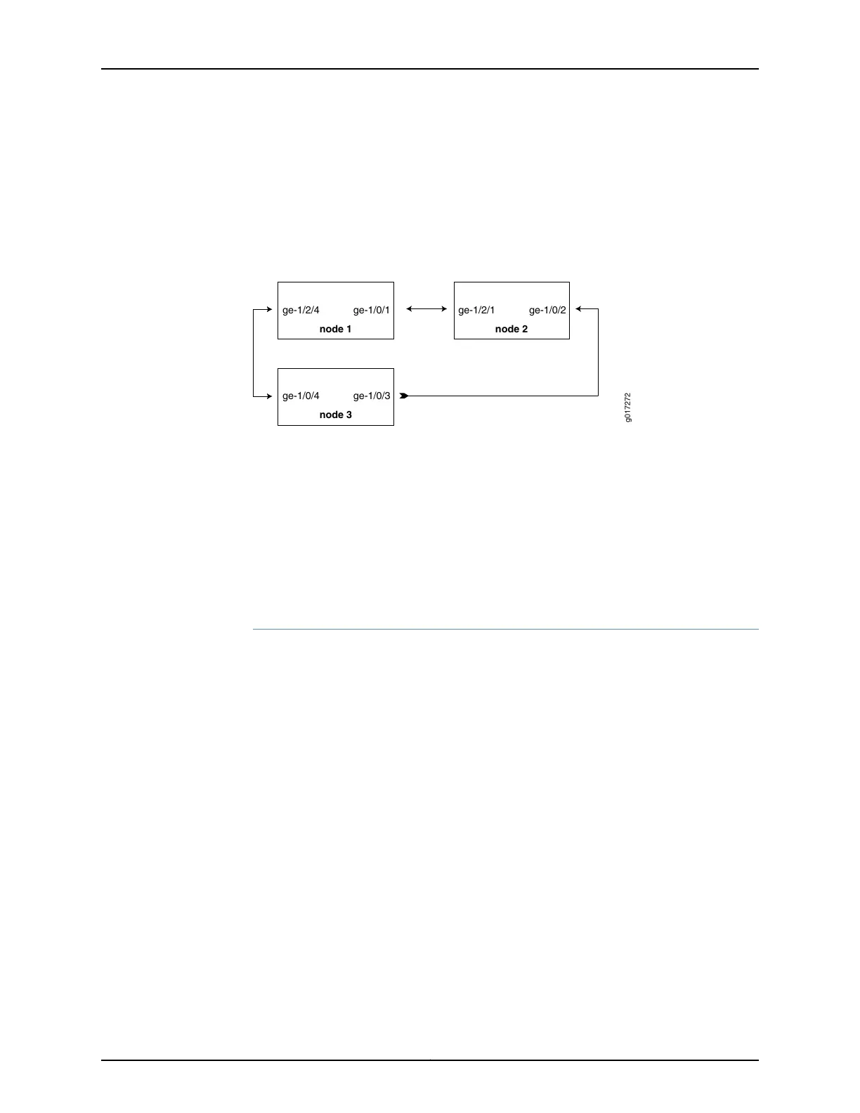
This section describes a configuration example for a three-node ring. The ring topology
is shown in Figure 17 on page 120.
Figure 17: Example of a Three-Node Ring Topology
g017272
ge-1/2/4 ge-1/0/1
node 1
ge-1/2/1 ge-1/0/2
node 2
ge-1/0/4 ge-1/0/3
node 3
The configuration in this section is only for the RAPS channel. The bridge domain for user
traffic is the same as the normal bridge domain. The only exception is if a bridge domain
includes a ring port, then it must also include the other ring port of the same ring.
Configuring a Three-Node Ring
To configure Ethernet Ring Protection Switching on a three-node ring, perform these
tasks:
•
Configuring Ethernet Ring Protection Switching on a Three-Node Ring on page 120
Configuring Ethernet Ring Protection Switching on a Three-Node Ring
Step-by-Step
Procedure
Configuring Node 1
interfaces {
ge-1/0/1 {
1.
vlan-tagging;
encapsulation flexible-ethernet-services;
unit 1 {
encapsulation vlan-bridge;
vlan-id 1;
}
unit 100 {
encapsulation vlan-bridge;
vlan-id 100;
}
}
ge-1/2/4 {
vlan-tagging;
encapsulation flexible-ethernet-services;
unit 1 {
encapsulation vlan-bridge;
vlan-id 1;
}
unit 100 {
encapsulation vlan-bridge;
vlan-id 100;
}
Copyright © 2017, Juniper Networks, Inc.120
ACX Series Universal Access Router Configuration Guide