This example is organized into the following sections:
•
Requirements on page 1305
•
Overview and Topology on page 1305
•
Configuration on page 1306
Requirements
This example uses the following hardware components:
•
Four MX Series 3D Universal Edge Routers for Routers PE1, PE2, PE3, and PE4
•
Two M Series Multiservice Edge Routers for Routers CE4 and PE5
•
Two EX Series Ethernet Switches for Devices CE1 and CE2
•
Two T Series Core Routers for Routers P1 and the route reflector
Overview and Topology
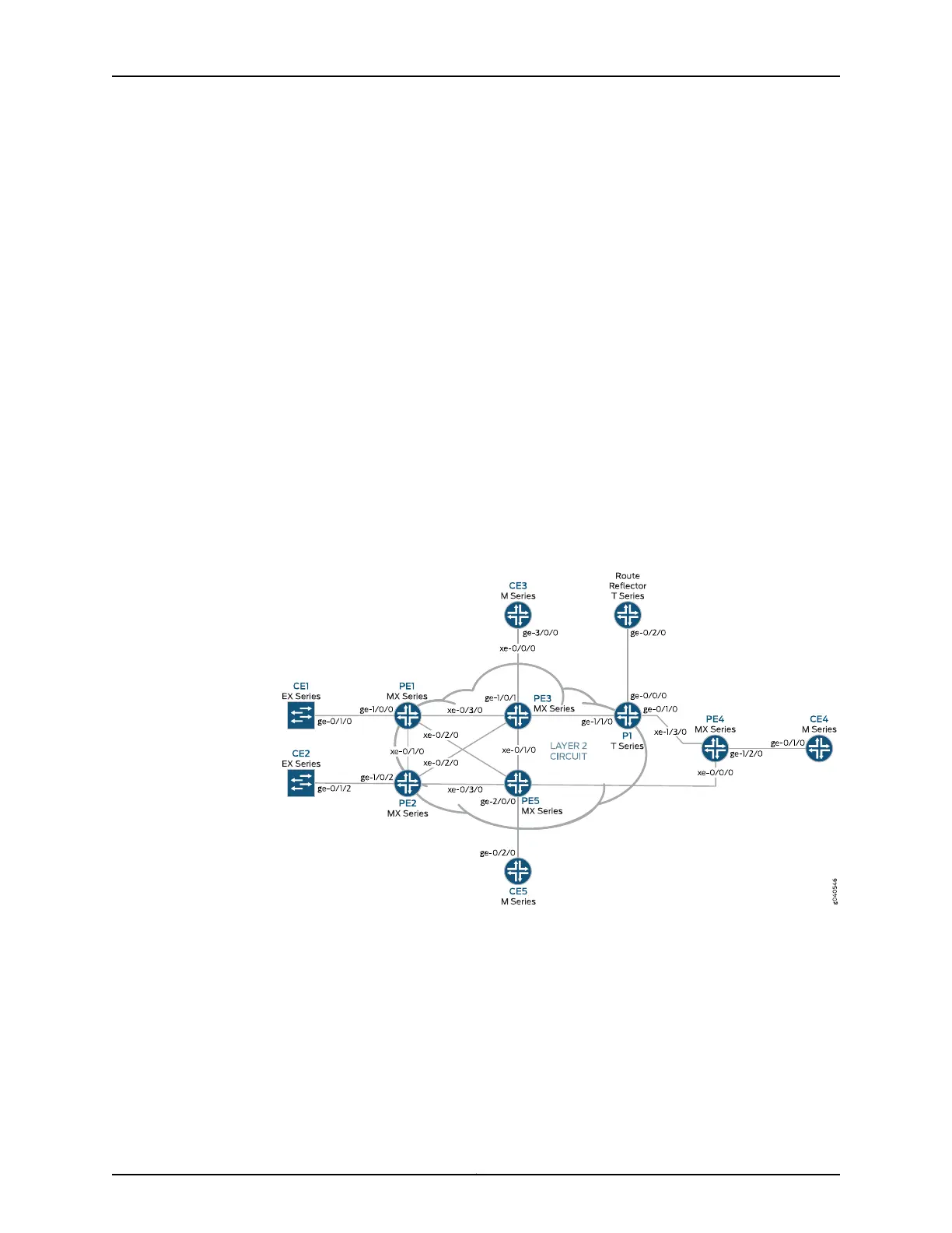
Figure 67 on page 1305 shows the physical topology used in this example.
Figure 67: Physical Topology of H-VPLS using a Single Mesh Group
In Figure 67 on page 1305:
•
Local switching is used to switch traffic between Layer 2 circuit pseudowires from the
different spoke PE routers.
•
The spoke PE routers are configured with the same virtual circuit ID and VPLS ID pair
in a mesh group.
•
The spoke PE routers are configured in an LDP-signaled VPLS routing instance.
•
The layer 2 circuits are terminated into the LDP-based VPLS.
1305Copyright © 2017, Juniper Networks, Inc.
Chapter 35: Configuring Virtual Private LAN Service

 Loading...


