Topology
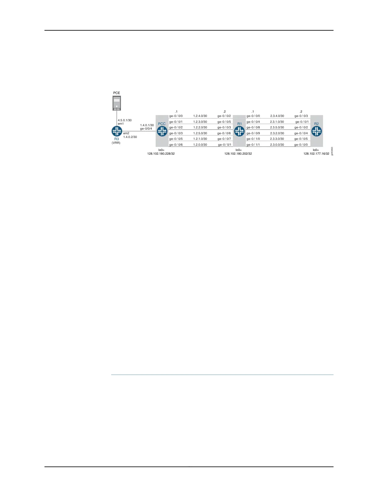
Figure 42: Example PCE-Controlled Point-to-Multipoint LSPs
ge-0 / 0/1 1.2.3.0/30 ge-0 / 0/5 ge-0 / 0/4 2.3.1.0/30 ge-0 / 0/1
ge-0 / 0/2 1.2.2.0/30 ge-0 / 0/3 ge-0 / 0/8 2.3.5.0/30 ge- 0 / 0/2
ge-0 / 0/3 1.2.5.0/30 ge- 0 / 0/6 ge-0 / 0/9 2.3.2.0/30 ge-0 / 0/4
ge-0 / 0/5 1.2.1.0/30 ge- 0 / 0/7 ge-0 / 1/0 2.3.3.0/30 ge- 0 / 0/5
ge-0 / 0/6 1.2.0.0/30 ge- 0 / 0/1 ge-0 / 1/1 2.3.0.0/30 g e- 0 / 0/0
PCE
lo0=
128.102.180.228/32
ge-0 / 0/0 1.2.4.0/30 ge-0 / 0/2 ge- 0 / 0/0 2.3.4.0/30 ge-0 / 0/3
.1 .2 .1 .2
lo0=
128.102.180.202/32
lo0=
128.102.177.16/32
em2
1.4.0.2/30
1.4.0.1/30
ge-0/0/4
4.5.0.1/30
em1
R3
(VRR)
g043463
PCC R1 R2
In this example, PCC is the ingress router, Router R1 is the transit router, and Router R2
is the egress router. PCC is connected to a Virtual Route Reflector (VRR) that is connected
to a PCE. There are many point-to-multipoint interfaces between PCC, Router R1, and
Router R2.
The reporting of point-to-multipoint LSPs is executed as follows:
1. If Router PCC is configured with point-to-point and point-to-multipoint LSPs without
the support for point-to-multipoint reporting capability, only the point-to-point LSPs
are reported to the connected PCE. By default, a PCC does not support
point-to-multipoint LSP reporting capability.
2. When Router PCC is configured with point-to-multipoint LSP reporting capability,
PCC first advertises this capability to PCE through a report message.
3. By default, a PCE provides support for point-to-multipoint LSP capability. On receiving
the PCC’s advertisement for point-to-multipoint LSP capability, the PCE in return
advertises its capability to the PCC.
4. On receiving the PCE’s advertisement of the point-to-multipoint capability, PCC
reports all branches of point-to-multipoint LSPs to the PCE using the update message.
5. Once all the LSPs are reported to the PCE, LSP state is synchronized between the
PCE and PCC.
Configuration
CLI Quick
Configuration
To quickly configure this example, copy the following commands, paste them into a text
file, remove any line breaks, change any details necessary to match your network
configuration, and then copy and paste the commands into the CLI at the [edit] hierarchy
level.
PCC set interfaces ge-0/0/0 unit 0 family inet address 1.2.4.1/30
set interfaces ge-0/0/0 unit 0 family mpls
set interfaces ge-0/0/1 unit 0 family inet address 1.2.3.1/30
Copyright © 2017, Juniper Networks, Inc.736
ACX Series Universal Access Router Configuration Guide