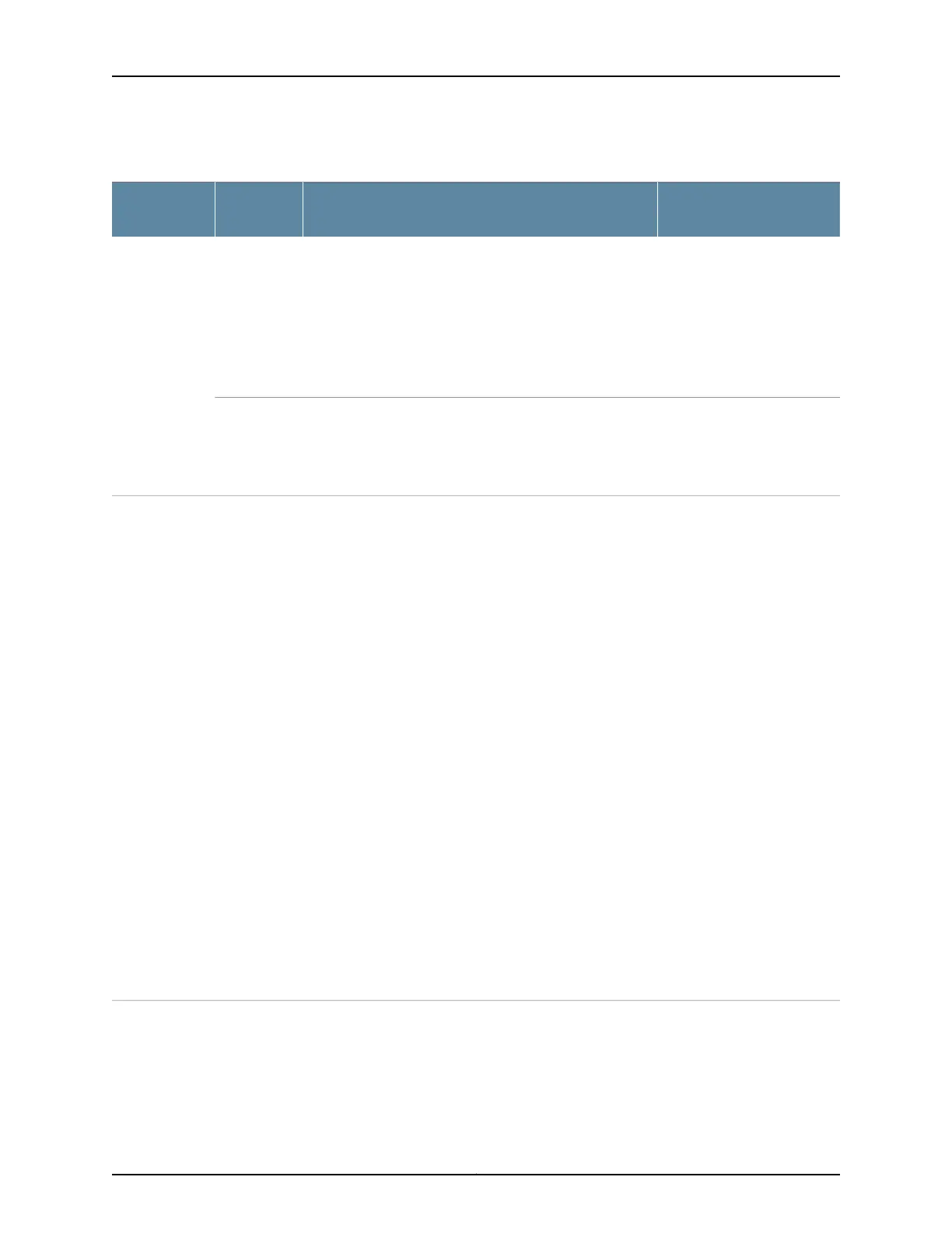
Table 148: Byte Count by Interface Hardware
CommentsByte Count Includes
Output
Level
Interface
Hardware
The 12 additional bytes
include 6 bytes for the
destination MAC address +
4 bytes for the VLAN + 2 bytes
for the Ethernet type.
For RED dropped, 6 bytes are
added for the source MAC
address.
Queued: 490 bytes per packet, representing 478 bytes of
Layer 3 packet + 12 bytes
Transmitted: 490 bytes per packet, representing 478 bytes
of Layer 3 packet + 12 bytes
RED dropped: 496 bytes per packet representing 478 bytes
of Layer 3 packet + 18 bytes
InterfaceGigabit
Ethernet IQ and
IQE PICs
–Queued: 478 bytes per packet, representing 478 bytes of
Layer 3 packet
Transmitted: 478 bytes per packet, representing 478 bytes
of Layer 3 packet
Packet
forwarding
component
The Layer 2 overhead is 14
bytes for non-VLAN traffic
and 18 bytes for VLAN traffic.
T Series, TX Series, T1600, and MX Series routers:
• Queued: 478 bytes of Layer 3 packet.
• Transmitted: 478 bytes of Layer 3 packet.
T4000 routers with Type 5 FPCs :
• Queued: 478 bytes of Layer 3 packet + the full Layer 2
overhead including 4 bytes CRC + the full Layer 1 overhead
8 bytes preamble + 12 bytes Inter frame Gap.
• Transmitted: 478 bytes of Layer 3 packet + the full Layer
2 overhead including 4 bytes CRC + the full Layer 1
overhead 8 bytes preamble + 12 bytes Interframe Gap.
M Series routers:
• Queued: 478 bytes of Layer 3 packet.
• Transmitted: 478 bytes of Layer 3 packet + the full Layer
2 overhead.
PTX Series Packet Transport Routers:
• Queued: The sum of the transmitted bytes and the RED
dropped bytes.
• Transmitted: Full Layer 2 overhead (including all L2
encapsulation and CRC) + 12 inter-packet gap + 8 for the
preamble.
• RED dropped: Full Layer 2 overhead (including all L2
encapsulation and CRC) + 12 inter-packet gap + 8 for the
preamble (does not include the VLAN header or MPLS
pushed bytes).
InterfaceNon-IQ PIC
Copyright © 2017, Juniper Networks, Inc.2552
ACX Series Universal Access Router Configuration Guide

 Loading...