show chassis craft-interface (M120 Router) on page 1869
show chassis craft-interface (M160 Router) on page 1870
show chassis craft-interface (vMX on NFX250) on page 1870
show chassis craft-interface (MX104 Router) on page 1871
show chassis craft-interface (MX2010 Router) on page 1871
show chassis craft-interface (MX2020 Router) on page 1872
show chassis craft-interface (MX2008 Router) on page 1873
show chassis craft-interface (T4000 Router) on page 1874
show chassis craft-interface (TX Matrix Routing Matrix) on page 1875
show chassis craft-interface (TX Matrix Plus Routing Matrix) on page 1877
show chassis craft-interface (TX Matrix Plus router with 3D SIBs) on page 1880
show chassis craft-interface (ACX2000 Universal Access Router) on page 1881
show chassis craft-interface (ACX500 Router) on page 1882
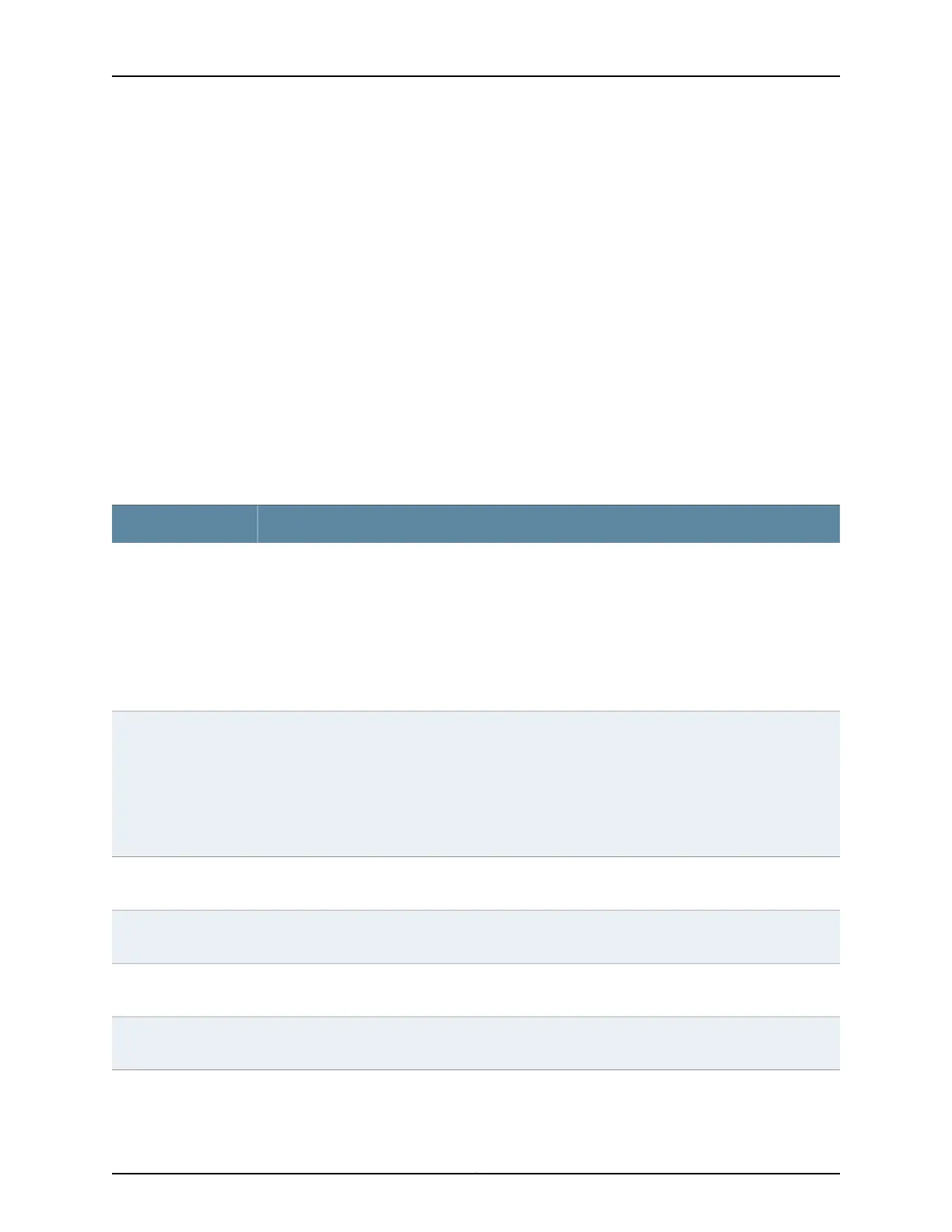
Output Fields Table 120 on page 1867 lists the output fields for the show chassis craft-interface command.
Output fields are listed in the approximate order in which they appear.
Table 120: show chassis craft-interface Output Fields
Field DescriptionField Name
Contents of the Front Panel Module display:
• router-name—Name of the router.
• Up—How long the router has been operational, in days, hours, minutes, and seconds.
• message—Information about the router traffic load, the power supply status, the fan status, and
the temperature status. The display of this information changes every 2 seconds. If a text message
has been created with the set chassis display command, this message appears on all four lines of
the craft interface display. The display alternates between the text message and the standard
system status messages every 2 seconds.
LCD screen
or
FPM Display Contents
(TX Matrix Plus Routers)—Display the SFC front panel switch settings:
SFC Chassis Number and Config Size are settings on physical switches located on the left side of the
craft interface of the TX Matrix Plus router.
• SFC Chassis Number—This field always displays the value 00.
• Config Size—The value of this field is 0 for the TX Matrix Plus router. The value of this filed is 3 for
TX Matrix Plus router with 3D SIBs.
SFC Front Panel Switch
Settings
(MX104, MX2010, MX2020, and MX2008 Routers) Status of the Front Panel System LEDs. A dot (.)
indicates the LED is not lit. An asterisk (*) indicates the LED is lit.
Front Panel System
LEDs
(MX104, MX2010, MX2020, and MX2008 Routers) Status of the Front Panel Alarm indicators. A dot
(.) indicates the relay is off. An asterisk (*) indicates the relay is active.
Front Panel Alarm
Indicators
Status of the configured input relay ports—0 through 3. The mode is normally open or closed. The
status is clear or raised.
Input Relay
Status of the configured output ports—0 or 1. The mode is normally open or closed. The status is clear
or raised.
Output Relay
1867Copyright © 2017, Juniper Networks, Inc.
Chapter 42: Operational Commands

 Loading...