• Stack member number—The number that identifies the switch within the stack. The range is 1 to 8 for
a stack of Catalyst 2960-X switches, and 1 to 4 for a mixed stack of Catalyst 2960-X and Catalyst 2960-S
switches. The switch number is assigned the first time the switch initializes. The default switch number,
before it is integrated into a switch stack, is 1. When a switch has been assigned a stack member number,
it keeps that number until another is assigned to it.
You can use the switch port LEDs in Stack mode to identify the stack member number of a switch.
• Module number—The module or slot number on the switch (always 0).
• Port number—The interface number on the switch. The 10/100/1000 port numbers always begin at 1,
starting with the far left port when facing the front of the switch, for example, gigabitethernet1/0/1 or
gigabitethernet1/0/8. For a switch with 10/100/1000 ports and SFP module ports, SFP module ports are
numbered consecutively following the 10/100/1000 ports.
You can identify physical interfaces by physically checking the interface location on the switch. You can also
use the show privileged EXEC commands to display information about a specific interface or all the interfaces
on the switch. The remainder of this chapter primarily provides physical interface configuration procedures.
These are examples of how to identify interfaces on a stacking-capable switch:
•
To configure 10/100/1000 port 4 on a standalone switch, enter this command:
Switch(config)# interface gigabitethernet1/0/4
•
To configure 10/100/1000 port 4 on stack member 3, enter this command:
Switch(config)# interface gigabitethernet3/0/4
Default Ethernet Interface Configuration
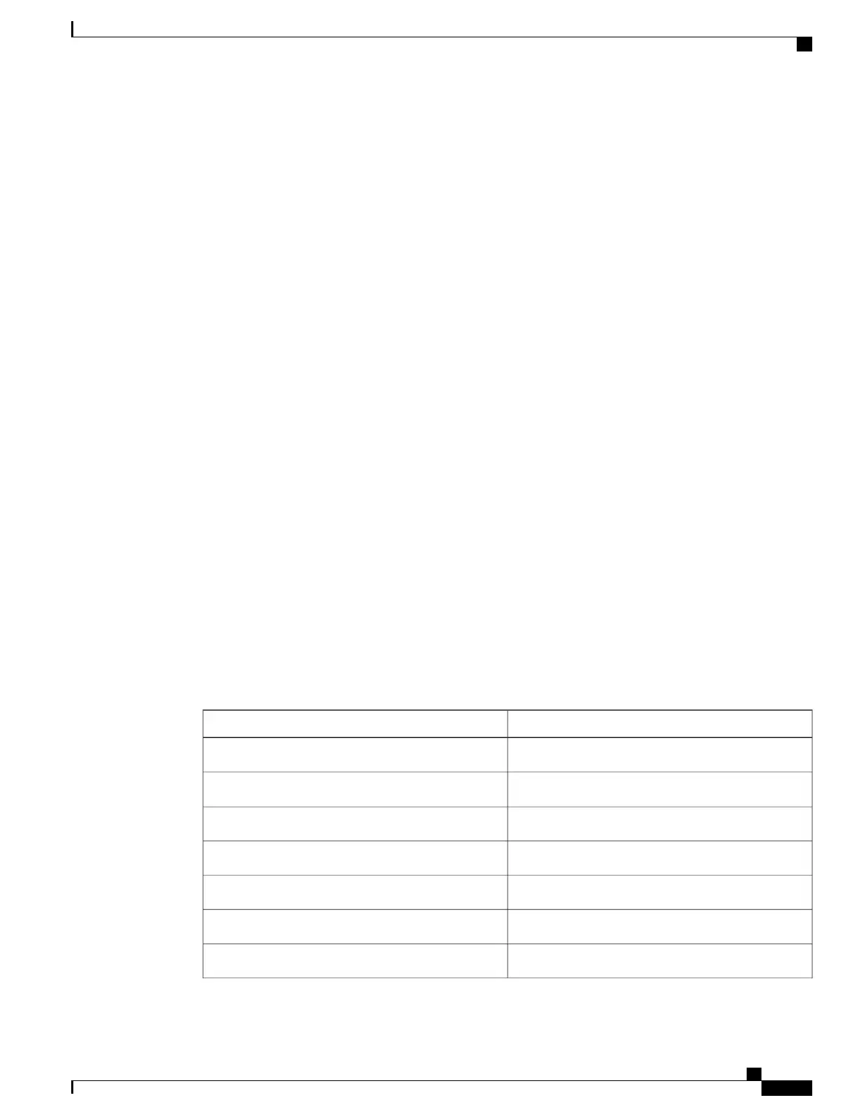
This table shows the Ethernet interface default configuration, including some features that apply only to Layer
2 interfaces.
Table 4: Default Layer 2 Ethernet Interface Configuration
Default SettingFeature
Layer 2 or switching mode (switchport command).Operating mode
VLANs 1– 4094.
Allowed VLAN range
VLAN 1.Default VLAN (for access ports)
VLAN 1.Native VLAN (for IEEE 802.1Q trunks)
Drop all packets tagged with VLAN 0.802.1p priority-tagged traffic
Switchport mode dynamic auto (supports DTP).VLAN trunking
All ports are enabled.Port enable state
Consolidated Platform Configuration Guide, Cisco IOS Release 15.2(4)E (Catalyst 2960-X Switches)
21
Information About Configuring Interface Characteristics